Apparatus for making particulates of controlled dimension

a technology of control dimension and electric motor, applied in the direction of magnetism of inorganic materials, magnetic bodies, magnetic materials, etc., can solve the problems of difficult and expensive control of thickness and shape of flat metallic particles, relatively thick flake, and low cost, and achieve the effect of low cos

Inactive Publication Date: 2006-05-30
THE BOEING CO
View PDF3 Cites 5 Cited by
  • Summary
  • Abstract
  • Description
  • Claims
  • Application Information

AI Technical Summary

Problems solved by technology

Flat metallic particles of controlled thickness and shape typically are difficult and expensive to make.
Ball milling results in relatively thick flake with little control of size and shape.
Vacuum deposition followed by a chemical or mechanical removal of particulates from the substrate is costly with little control of shape of the flake.
Pre-existing flake shapes are typically too thick and the shape too jagged for high performance coatings.
Thin film metal particulates are expensive, because existing process to make them, like those described in U.S. Pat. No. 4,879,140 or 5,100,599, use exotic equipment such as plasma generators or vacuum chambers, or are labor intensive, small scale processes like photolithography.
The equipment cost and relative slow rate of production using skilled labor to operate the sophisticated equipment increases the cost The prior art particulates are not readily produced in reasonable volume, and cost as much as $5,000 / oz.
At these prices, paints that use the particulates as the pigment are only suitable for highly specialized applications.
Working with hydrazine, however, on a commercial scale poses safety questions.
Such flakes tended to curl and were unacceptable for batteries because of their shape.
Also, they were too thick.

Method used


Image

  • Apparatus for making particulates of controlled dimension
  • Apparatus for making particulates of controlled dimension
  • Apparatus for making particulates of controlled dimension

Examples


examples

[0073]The following examples show several trials in which we have demonstrated the process of the present invention to produce iron flake, gold flake, and iron-cobalt flake.

Iron Flake

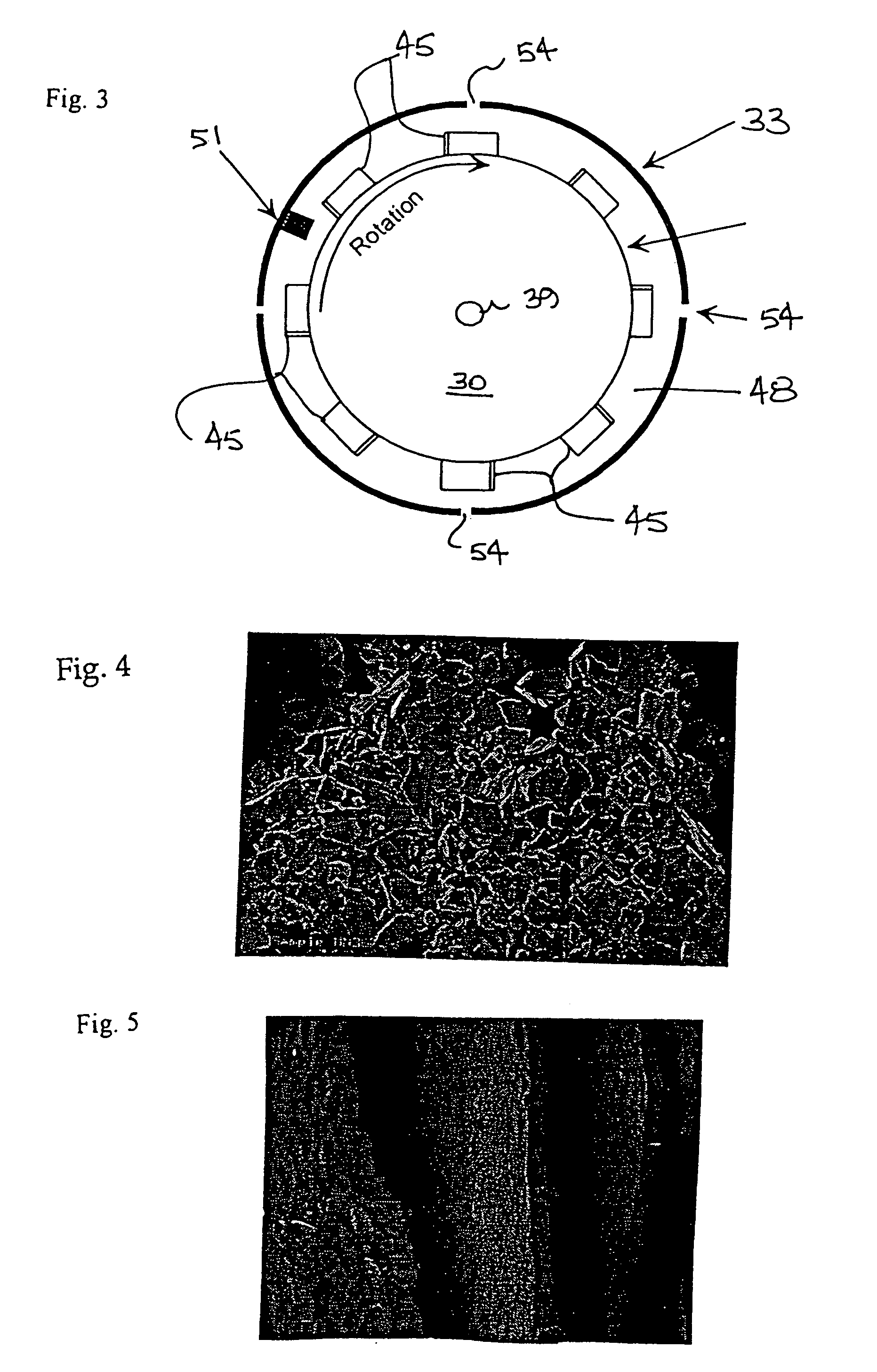
[0074]1. Mix 192 g ferrous sulfate heptahydrate in 1000 ml of deoxygenated, deionized water.[0075]2. Turn on filtering / collection system. Bubble nitrogen through the bath.[0076]3. Place a carbon steel anode (1015 steel), and a flat, polished titanium (6A1-4V) cathode, like that in FIG. 5, into bath in opposing positions and hook up electrical connections.[0077]4. With a rectifier, apply a current density of 20 to 40 amps per square foot for 8 seconds.[0078]5. With a sonicator at approximately 80% power for 20 seconds, sweep across total area of cathode, approximately 1 inch away from cathode.[0079]6. Repeat steps 4 and 5 to prepare the desired amount of particles.[0080]7. Collect particles magnetically in the filtering / collection system.

[0081]FIGS. 4 and 5 show typical iron flake made by this process.

Go...


PUM

PropertyMeasurementUnit
pressuresaaaaaaaaaa
temperaturesaaaaaaaaaa
diameteraaaaaaaaaa

Abstract

We make particulates, especially magnetic Fe—Co alloys having high magnetic permeability, of controlled dimensions, especially those having a narrow thickness size distribution centered around a median or target thickness in the range of about 0.1–1.0 μm, using electrodeposition typically on a smooth (polished) titanium cathode. Our preferred continuous process uses a rotating drum cathode inside a fixed anode to grow flakes and to produce them automatically by inherent instability in the deposited film. The drum preferably rotates about a substantially vertical axis. The particulates shed (slough off) into the electrolyte (because of mismatch between the cathode surface and the plated metal or alloy at the molecular level) where they are separated in a magnetic separator or other suitable device. If the flakes are soft iron or iron-cobalt alloys, the drum generally is titanium or titanium alloy.

Description

REFERENCE TO RELATED APPLICATION[0001]The present application is a divisional application based upon U.S. patent application Ser. No. 09 / 967,248, filed Sep. 28, 2001 now U.S. Pat. No. 6,699,579, which was a divisional application based upon U.S. patent application Ser. No. 09 / 330,925, filed Jun. 14, 1999 now U.S. Pat. No. 6,376,063, which claims the benefit of U.S. Provisional Patent Application 60 / 089,328, filed Jun. 15, 1998.TECHNICAL FIELD[0002]The present invention relates to an electroplating apparatus for making particulates of controlled dimensions (especially magnetic Fe—Co ones).BACKGROUND OF THE INVENTION[0003]Flat metallic particles of controlled thickness and shape typically are difficult and expensive to make. Ball milling results in relatively thick flake with little control of size and shape. Vacuum deposition followed by a chemical or mechanical removal of particulates from the substrate is costly with little control of shape of the flake. Vacuum / chemical vapor depos...

Claims


Application Information

Patent Timeline
Patent Type & Authority Patents(United States)
IPC IPC(8): C25B11/03B22F1/068C22C33/02C25C5/02H01F1/00H01F1/20H01F1/44H01F41/16H01F41/26
CPCB22F1/0055C25C5/02H01F1/0027H01F1/20H01F1/442H01F41/16H01F41/26C25D1/00C25D1/20C22C33/0278Y10T428/256Y10S428/935Y10S428/926Y10S428/925Y10T428/2982Y10T428/2991B22F1/068
Inventor RASMUSSEN, GLEN L.DICKSON, MICHEAL E.MILLER, ROBERT J.NELSON, MARY J.HUGHES, JONATHAN C.RAWLINGS, DIANE C.
Owner THE BOEING CO
Why Eureka
Try Eureka