
Linear lambda probe evaluation circuit

a lambda probe and evaluation circuit technology, applied in the direction of instruments, material electrochemical variables, optical radiation measurement, etc., can solve the problems of deviation in the transformation ratio, unsuitable measurement, complex design of linear lambda probes, etc., and achieve the effect of significant improvement in measurement precision

Inactive Publication Date: 2006-05-30
CONTINENTAL AUTOMOTIVE GMBH
View PDF6 Cites 1 Cited by
  • Summary
  • Abstract
  • Description
  • Claims
  • Application Information

AI Technical Summary

Benefits of technology

[0025]The object of the invention is to improve the known device for operating a linear lambda probe to the effect that values of the pumping current Ip which correspond to the requirements set are made available, that the common mode error which is described is avoided and the precision of the measurement is significantly improved, and that the probe is still operationally capable even when the battery voltage is low (Vb=+6 V).

Problems solved by technology

These probes have an extremely restrictive measuring range about λ=1 and are therefore unsuitable for measurements in the lean operating mode λ>1.
The linear lambda probe is of complex design.
This would result in a deviation in the transformation ratio (amplification error).
Furthermore, the dynamic resistance of the diffusion barrier has a temperature dependence, which in turn leads to errors in the transmission ratio.
Alternatively, a higher supply voltage of the circuit could be used, for example 8 V. However, this would have the disadvantage that an additional expensive voltage controller would be necessary and the circuit would no longer function when the battery voltage is low (<8.5 V).
In addition, the polarization voltage of the pumping cell (−350 mV when λ<1) results in a zero point error ΔIp of approximately 5 μA.
As the pumping current Ip is the primary measurement signal of the oxygen probe, these errors directly affect the overall precision of the probe measurement signal.
This restricts the precision of the lambda control and thus constitutes a significant problem.

Method used


Image

  • Linear lambda probe evaluation circuit
  • Linear lambda probe evaluation circuit

Examples


Embodiment Construction

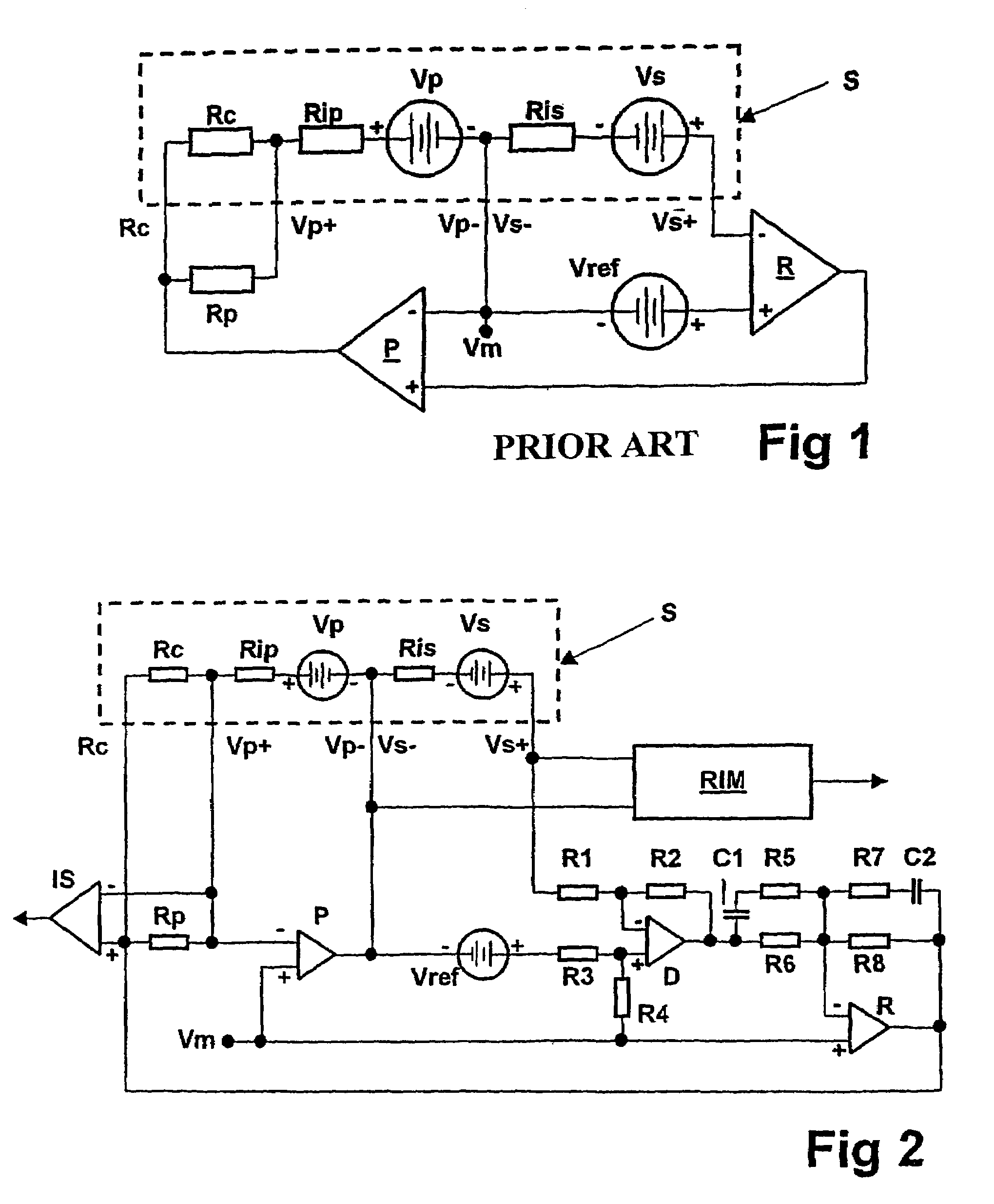
[0039]FIG. 1 shows a basic circuit diagram of the known device for operating a linear lambda probe of an internal combustion engine in the region λ=1.

[0040]The lambda probe S is composed[0041]a) of what is referred to as the reference cell, i.e. of the electrodes between the measuring chamber and air, represented in the drawing by the Nernst voltage Vs which can be measured between the electrodes, and the internal resistance Ris of the diffusion barrier between them,[0042]b) of what is referred to as the pumping cell, i.e. of the electrodes between the measuring chamber and exhaust gas, represented by the voltage Vp which drops between them and the (reference) resistance Rip between these electrodes, and[0043]c) of the calibrating resistor Rc in the probe plug.

[0044]The electrodes are applied to the ceramic body of the probe. The ceramic material between the pairs of electrodes is conductive at high temperatures and is used as a solid electrolyte.

[0045]As the resistor Rc is subject ...


PUM

PropertyMeasurementUnit
voltageaaaaaaaaaa
voltageaaaaaaaaaa
voltageaaaaaaaaaa

Abstract

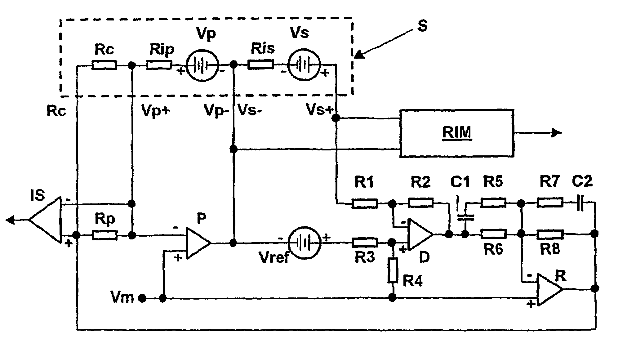
The pumping current source (P) required for operating the linear lambda probe is wired in such a manner that its inverting input is connected to the third probe terminal (Vp+), its non-inverting input is connected to the potential of the mean voltage (VM), and that its output is connected to the second probe terminal (Vp− / Vs−).

Description

CROSS REFERENCE TO RELATED APPLICATION[0001]This application is a continuation of copending International Application No. PCT / DE01 / 02165 filed Jun. 11, 2001 which designates the United States, and claims priority to German application number 10029794.3 filed Jun. 16, 2000.BACKGROUND OF THE INVENTION[0002]The invention relates to a device for operating a linear lambda probe of an internal combustion engine.[0003]Legislators are using tax incentives to promote the development of motor vehicles with increasingly low emissions of pollutants and fuel consumption. In spark ignition engines with stoichiometric mixture formation (λ=1), this has led to the development of SULEV vehicles (Super Ultra Low Emission Vehicles) with extremely low emissions.[0004]In order to save fuel, engines with direct HPDI (High Pressure Direct Injection) fuel injection are currently being developed and launched onto the market. The fuel is injected directly into the combustion chamber here at an increased press...

Claims


Application Information

Patent Timeline
Patent Type & Authority Patents(United States)
IPC IPC(8): G01N27/409G01N27/41G01N27/419G01N27/406
CPCG01N27/4065G01N27/41
Inventor BOLZ, STEPHAN
Owner CONTINENTAL AUTOMOTIVE GMBH
Learn More