Tuning fuel composition for driving cycle conditions in spark ignition engines

a technology of spark ignition engine and fuel composition, which is applied in the direction of fuels, machines/engines, mechanical equipment, etc., can solve the problems of limited use of high compression ratio spark ignition engine, damage to the engine, and damage to the overall performance, so as to maximize the engine thermal efficiency and prevent knocking

Inactive Publication Date: 2006-05-30
TOYOTA JIDOSHA KK
View PDF38 Cites 4 Cited by
  • Summary
  • Abstract
  • Description
  • Claims
  • Application Information

AI Technical Summary

Benefits of technology

[0013]One aspect of the invention is the provision of a plurality of unleaded fuel compositions for use in operating a spark ignition, internal combustion engine, especially an engine having a CR of 11 or more, each of which compositions have different predetermined combustion properties suitable for use under preselected engine operating conditions to improve one or more of fuel efficiency and combustion emissions.

Problems solved by technology

Both petroleum refineries and engine manufacturers are constantly faced with the challenge of continually improving their products to meet increasingly severe governmental efficiency and emission requirements, and consumers' desires for enhanced performance.
For example, engine manufacturers endeavor to inhibit to the maximum extent possible the phenomenon of auto-ignition which typically results in knocking and, potentially engine damage, when a fuel with insufficient knock-resistance is combusted in the engine.
This naturally requires compromise, as often times fuel properties or engine parameters that are desirable under certain speed / load conditions prove detrimental to overall performance at other speed / load conditions.
The use of high compression ratio spark ignition engines, however, is limited by insufficiently high fuel octane, as in practice it is difficult to supply a single fuel with sufficiently high octane overall to allow for a significant increase in compression ratio without having engine knocking at high loads.
Experience has shown, however, that adjusting the ignition timing to allow MBT to be reached is not practical since knocking typically occurs under conditions of moderate to high load at timings earlier than MBT with commercially available gasolines.
One challenge associated with operating the engine lean is the difficulty of establishing a rapid and complete burn of the fuel.
As known in the art, autoignition of the fuel at sufficiently high loads can pose a threat of mechanical damage to the engine, i.e., knocking.

Method used


Image

  • Tuning fuel composition for driving cycle conditions in spark ignition engines
  • Tuning fuel composition for driving cycle conditions in spark ignition engines
  • Tuning fuel composition for driving cycle conditions in spark ignition engines

Examples


example 1

[0046]The effects of a high octane, high knock-resistant, high burn rate fuel on combustion efficiency and performance were investigated in an in-line 4-cylinder (2.0 L displacement) DOHC 4 valve / cylinder direct injection spark ignition engine with a shell-shaped piston cavity, a straight intake air port, and a fan-shaped fuel spray. The engine was operated at high load / wide open throttle (WOT) at a compression ratio of 13.0. The base fuel was pure iso-octane with RON=100. The test fuel, called “DF-2” was comprised of 60% toluene, 33% iso-octane, and 7% n-heptane (measured RON=103). The fuel properties are listed in Table 1. Both fuels were combusted under the following conditions: engine speed=4000 rpm, fuel / air ratio (φ)=1.15, spark advance timing=11–24 degrees before top dead center (BTDC). In this example and the others that follow, the injection quantities of the fuel are adjusted so as to maintain equivalent total heating values

[0047]

TABLE 1FUEL PROPERTIES FOR WOT TESTSTest Fu...

example 2

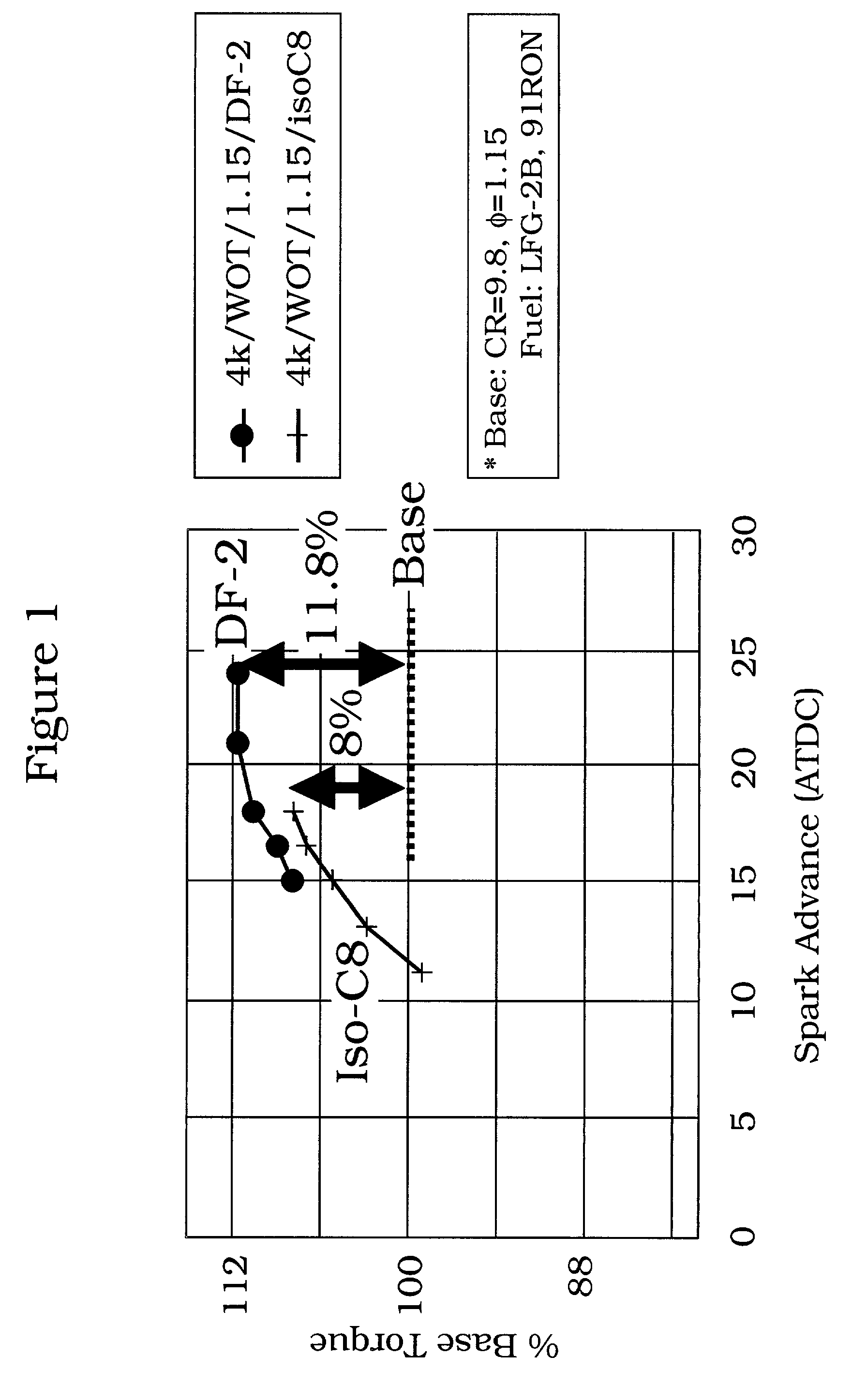
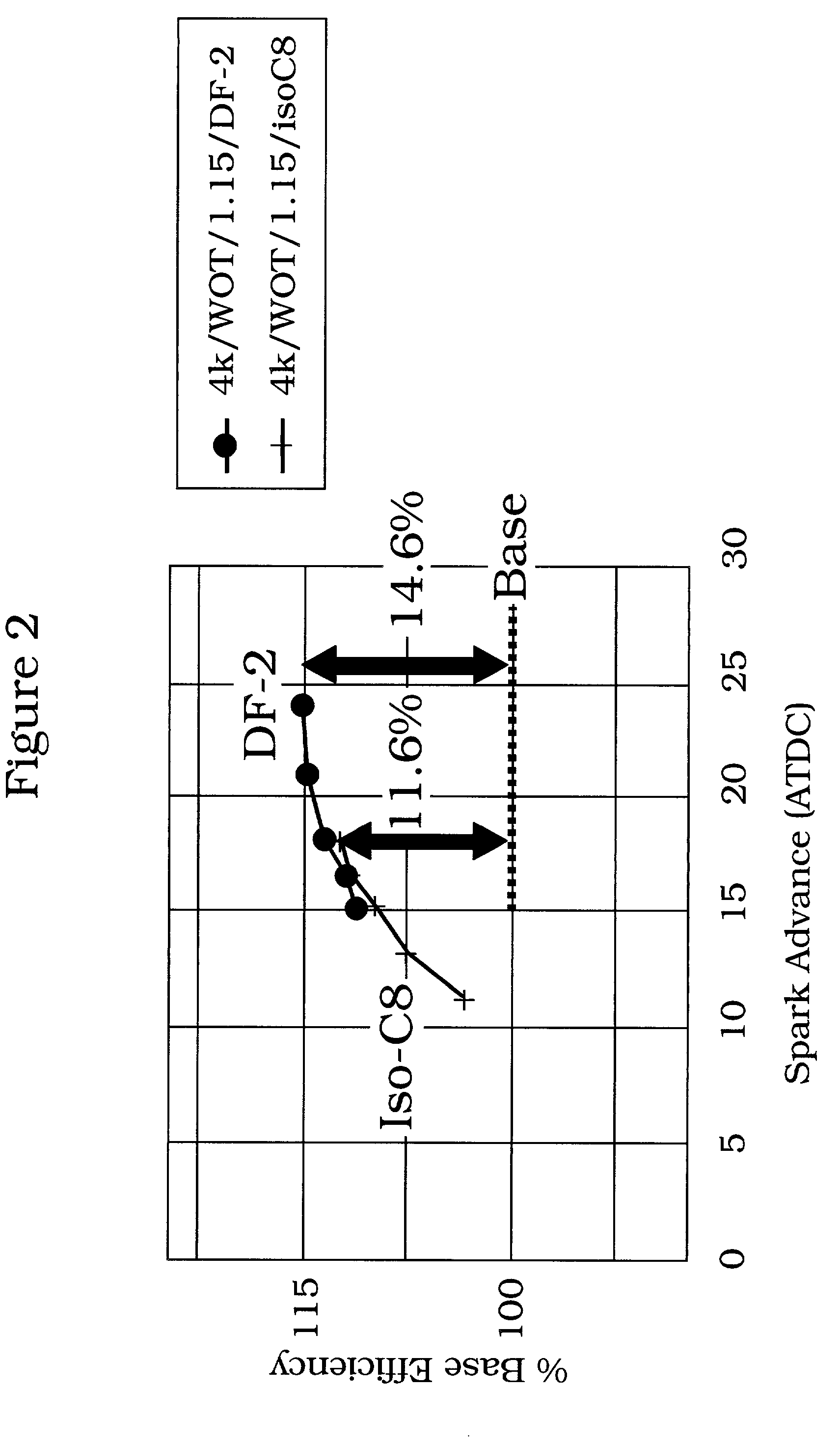
[0053]The effects of a low octane, low autoignition-resistant, high burn rate fuel on combustion efficiency and performance were investigated the same in-line 4-cylinder (2.0 L displacement) DOHC 4 valve direct injection spark ignition engine described in Example 1. The engine was operated at various low and moderate load conditions at a compression ratio of 9.8 and 13.0. The base fuel was a commercial Japanese regular gasoline, named LFG-2B, with a RON value of 91.7. The low octane test fuel, named DF-1, was comprised of 68% iso-octane, 22% n-heptane, and 10% toluene (measured RON=83.8). The fuel properties are shown in Table 3:

[0054]

TABLE 3Fuel PropertiesDF-1Test FuelMeasuredCalculatedRON91LFG-2BDensityp / cm3 @ 15 C.0.70910.70940.69310.7358RON—83.88079191.7NON—82.2?9182.7LHVk / g43.9144.543.0H / Cmol / mol2.1542.1122.251.87A / F stoich14,90015.114.7Viscositymm 2 / s @0.60330 C.DistillationIBPDeg C.95.0Approx.31.699T5Deg. C.98.042.5T10Deg C.98.050.5T20Deg C.98.562.0T30Deg C.98.572.5T40Deg C.9...

example 3

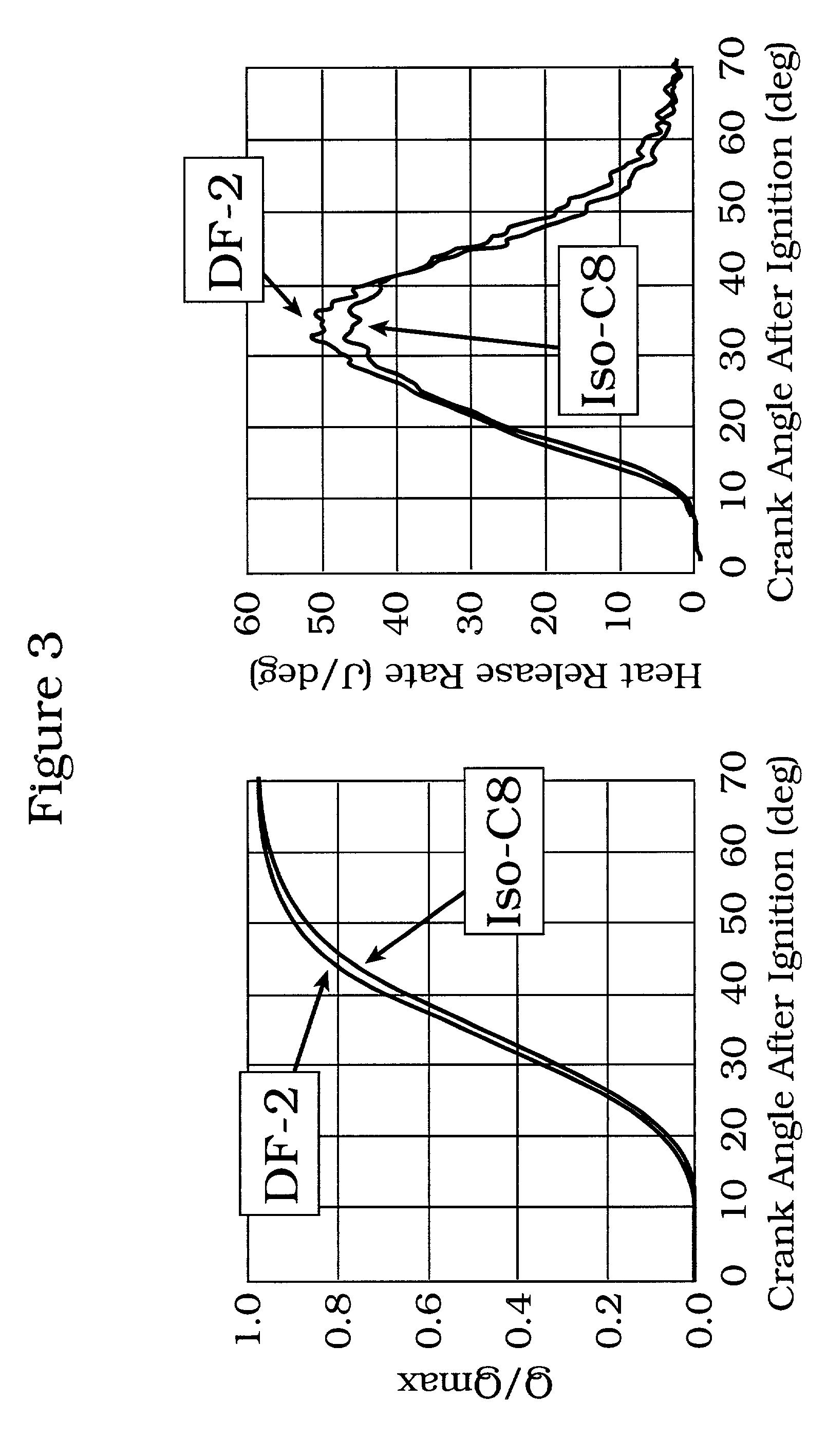
[0058]The effects of a low octane, low autoignition-resistant, high burn rate fuel on combustion efficiency and performance have been investigated at a different region of the driving cycle in the same in-line 4-cylinder (2.0 L displacement) DOHC 4 valve direct injection spark ignition engine described in Examples 1 and 2. The engine was operated at an engine speed of 3000 rpm and fuel / air ratio of φ=0.56, which is located on a different part of the speed / load map than the engine conditions described in Example 2. The engine was operated at a compression ratio of 9.8 and 13.0. The base fuel was a commercial Japanese regular gasoline, named LFG-2B, with a RON value of 91.7. The low octane test fuel, named DF-1, is the same fuel described in Example 2, and is comprised of 68% iso-octane, 22% n-heptane, and 10% toluene (measured RON=83.8). The fuel properties are shown in Table 3: As was observed under the engine operating conditions of Example 2, significantly lower NOx and smoke emis...


PUM

PropertyMeasurementUnit
compression ratioaaaaaaaaaa

Abstract

Tuning fuel composition delivered to a spark ignition, internal combustion engine as a function of driving cycle conditions results in improvements in one or more of fuel efficiency and combustion emissions.

Description

FIELD OF INVENTION[0001]The present invention relates generally to engine fuel compositions and their use in port or direct fuel injection spark ignition, internal combustion engines especially those having a compression ratio (CR) of 11 or more.BACKGROUND OF INVENTION[0002]Both petroleum refineries and engine manufacturers are constantly faced with the challenge of continually improving their products to meet increasingly severe governmental efficiency and emission requirements, and consumers' desires for enhanced performance. For example, in producing a fuel suitable for use in an internal combustion engine, petroleum producers blend a plurality of hydrocarbon containing streams to produce a product that will meet governmental combustion emission regulations and the engine manufacturers performance fuel criteria, such as research octane number (RON). Similarly, engine manufacturers conventionally design spark ignition type internal combustion engines around the properties of the f...

Claims


Application Information

Patent Timeline
Patent Type & Authority Patents(United States)
IPC IPC(8): C10L1/04C10L1/06F02D19/08
CPCC10L1/06F02D19/0649F02D19/081Y02T10/36F02D19/0689Y02T10/30
Inventor WEISSMAN, WALTERFARRELL, JOHN T.SCHILOWITZ, ALAN M.JOHNSTON, JOHN E.UEDA, TAKANORIAKIHAMA, KAZUHIRO
Owner TOYOTA JIDOSHA KK
Why Eureka
Try Eureka