
Separation System

a separation system and separation method technology, applied in the direction of separation processes, physical/chemical process catalysts, bulk chemical production, etc., can solve the problems of high energy expenditure, difficult movement of solids through the adsorption apparatus or system, and difficult separation of components by distillation. , to achieve the effect of reducing the requirements of pumping and distillation, increasing the efficiency of adsorption apparatus or system, and reducing contamination

Active Publication Date: 2011-10-06
EXXONMOBIL CHEM PAT INC
View PDF4 Cites 11 Cited by
  • Summary
  • Abstract
  • Description
  • Claims
  • Application Information

AI Technical Summary

Benefits of technology

[0029]In embodiments the process achieves improvements in one or more of efficiency of adsorption separation, capacity of adsorption apparatus systems, decrease in energy requirements (particularly in the aspects of pumping and distillation requirements, and purity of product attainable by adsorption process.
[0036]It is an object of the invention to decrease pumping and distillation requirements in the purification of material utilizing a simulated moving bed adsorptive separation system.
[0038]It is an additional object of this invention to increase the capacity of an adsorption apparatus or system. It is an advantage of this process that excess capacity of the apparatus or system may be more fully utilized by purifying the solids with flushing media and flushing conduits with media containing the desired component(s). It is a feature of such embodiments that fluid communication conduits may be flushed with media containing concentrations of a desired component or components higher than that of the feedstream, which may be drawn from a source other than the apparatus.
[0040]It is yet still further an object of this invention to eliminate or reduce the circulation requirements of the desorbent, including downstream distillation and separation of the adsorbent from the various solutes contained therein, the solutes including the desired component (such as, in the case of xylenes, one particular isomer, which is generally paraxylene).

Problems solved by technology

Some fluid mixtures comprise components which have similar boiling points, and in such cases, separation by distillation may be a difficult and an inefficient means to separate these components.
Too many contaminants, e.g., unwanted components, also may evaporate along with (or fail to evaporate from) the desired component(s), or the separation may require high energy expenditures due to the recycling through the distillation process that may be necessary to attain a desired degree of separation or purity.
Nevertheless, moving the solids through an adsorption apparatus may be difficult and involve complex machinery to move trays or beds.
It also may result in loss of the solids by attrition.
This can result in reduced product purity due to contamination of the withdrawn product.
Fluid communication conduits may contain unwanted components, such as residue remaining in the conduit from earlier additions or withdrawals of streams.
Nevertheless, flushing conduits with the product reduces the output of the adsorption process.
Having only a single flush does result in a slight compromise in the separation process, but the compromise typically is far outweighed by the benefit of optimizing the feed location of the paraxylene concentrate as far as net purity in the final product.
There is a problem with the above configuration in that the standard Parex unit has the secondary flush located close to the extract withdrawal point in order to minimize contaminants that are withdrawn with the extract.
However, when the secondary flush is very close to the extract withdrawal point and concentrated paraxylene (having associated impurities) is being flushed from the bed line, the configuration will be too close to the extract withdrawal point and the highest separation of the feed will not be realized.
All of these processes are still very energy-intensive due, at least in part, to the intensive use of materials such as the desorbent, which is typically reused after purification downstream of the bed systems described above.

Method used


Image

  • Separation System
  • Separation System
  • Separation System

Examples


Embodiment Construction

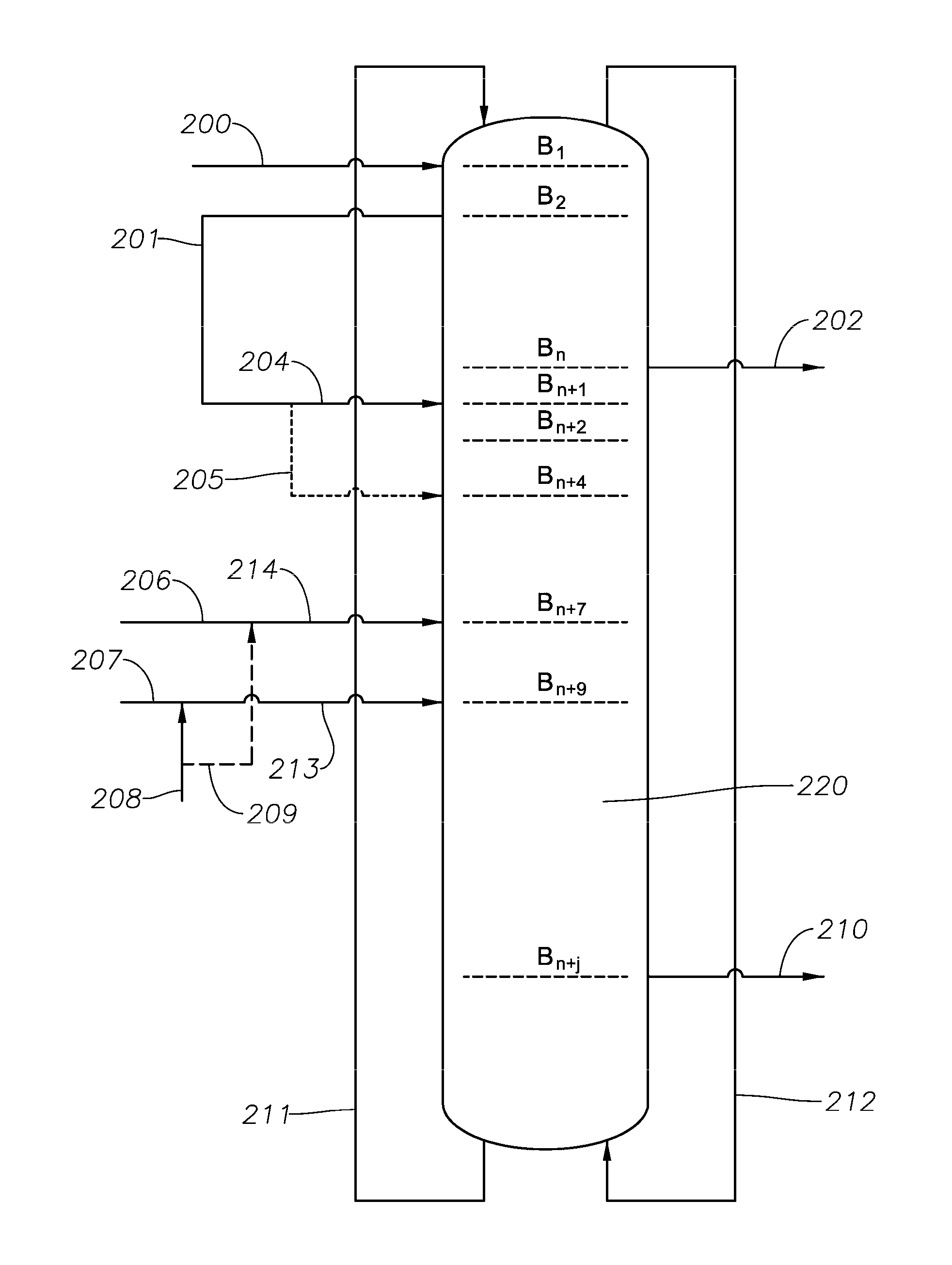
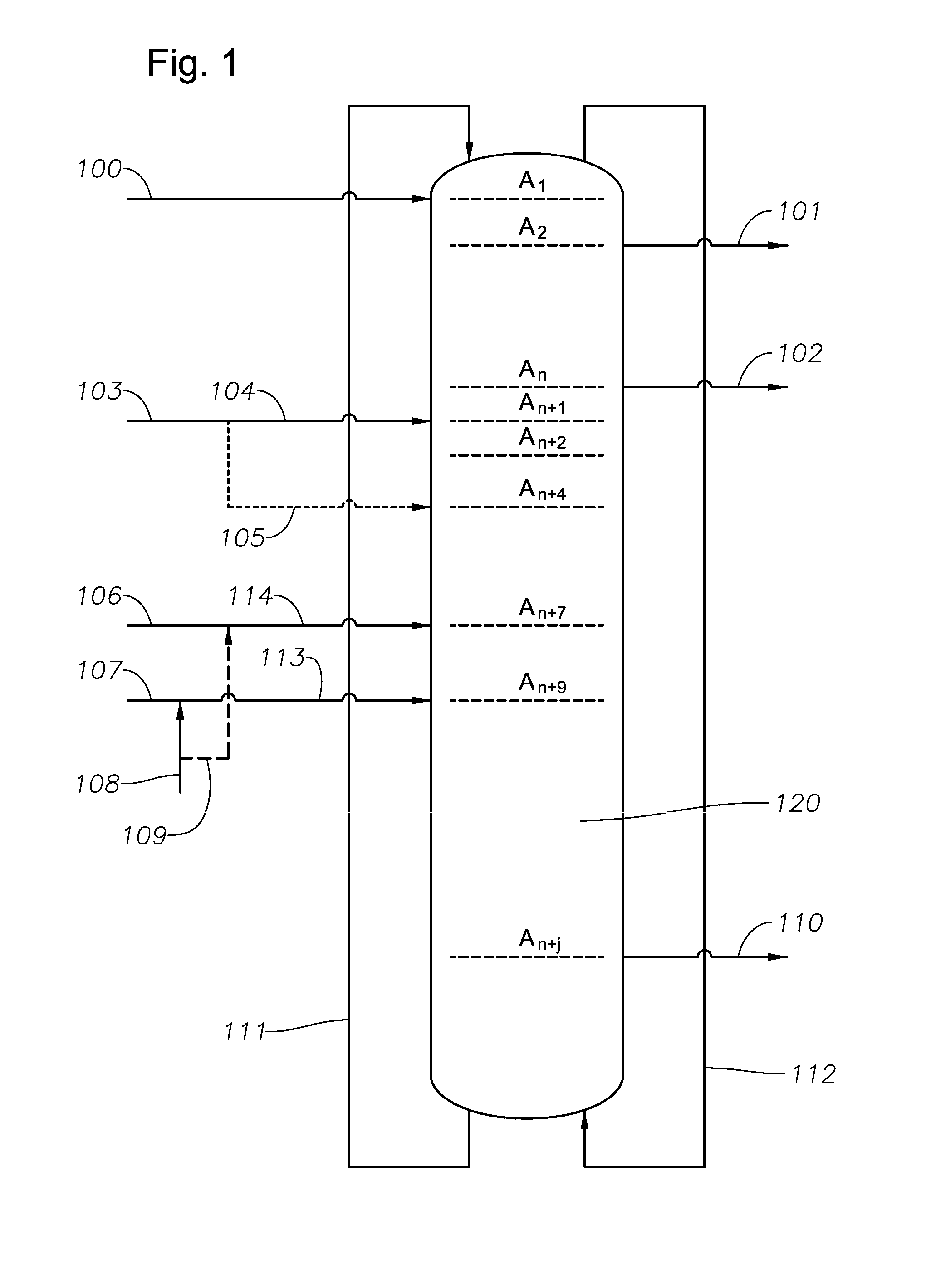
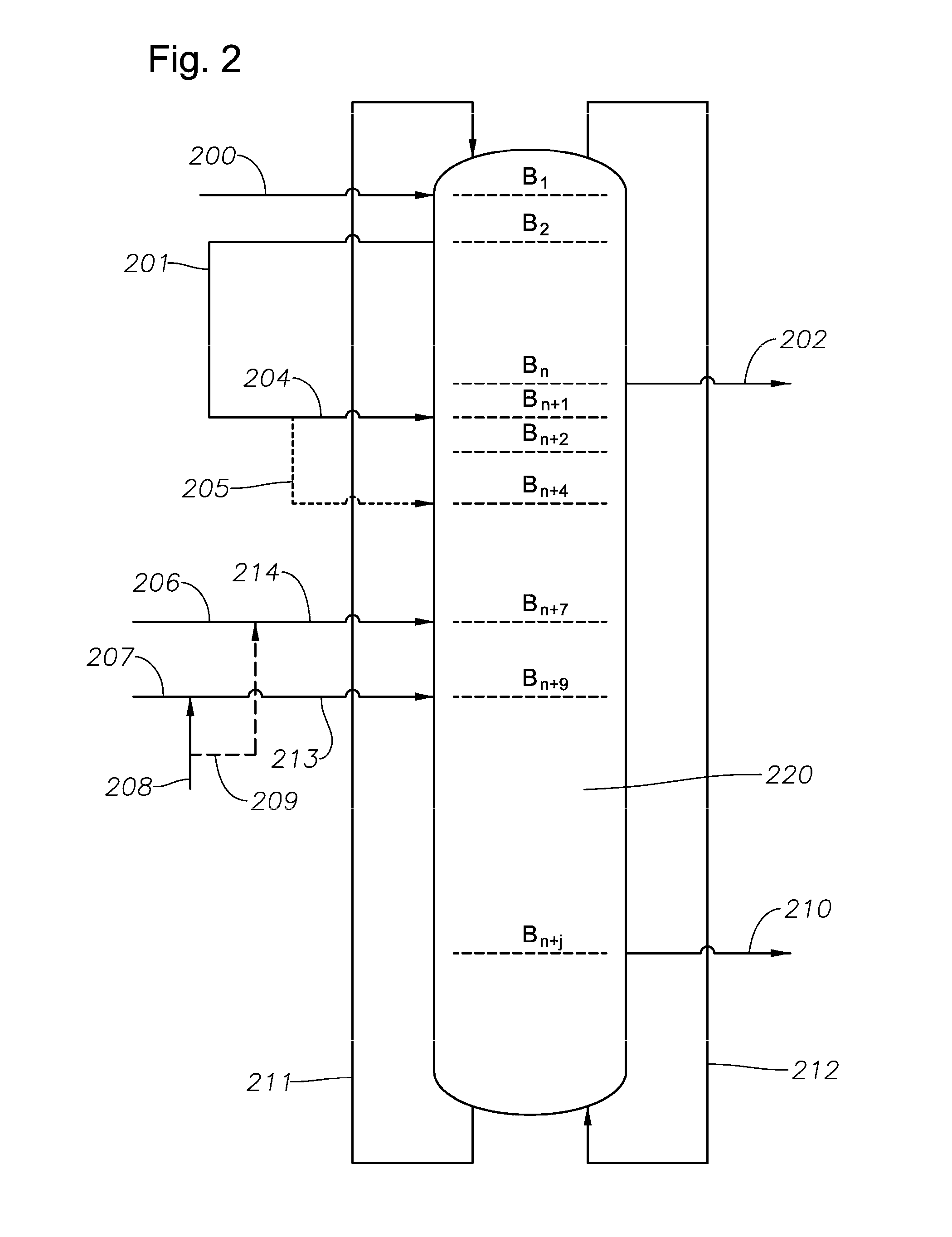
[0045]According to the invention, there is provided a process for separating a product from at least two multicomponent feeds to an adsorption apparatus or system. In an embodiment there is a simulated moving bed adsorptive separation system plumbed so that the first or primary flush output is connected to the secondary flush input directly, whereby the primary flush output, comprising desorbent and having a higher concentration of the desired compound as compared to the flush material prior to being used as primary flush, is then utilized as secondary flush input, resulting, in more preferred embodiments, in the secondary flush output comprising desorbent and having even higher concentration of the desired compound than in the primary flush input.

[0046]The apparatus or system may comprise a moving-bed or a simulated moving-bed adsorption means, and in embodiments provides a product comprising at least one organic compound, such as an aryl compound with alkyl substitutes, for instan...


PUM

PropertyMeasurementUnit
Concentrationaaaaaaaaaa
Purityaaaaaaaaaa
Aromaticityaaaaaaaaaa

Abstract

A process for separating a product from a multicomponent feedstream to an adsorption apparatus or system is described. The apparatus or system may comprise a moving-bed or a simulated moving-bed adsorption means. The product comprises at least one organic compound, such as an aryl compound with alkyl substitutes. In embodiments the conduits used to supply the feedstream to the apparatus or system are flushed with media of multiple grades. The improvement is more efficient use of the desorbent. In embodiments the process achieves improvements in one or more of efficiency of adsorption separation, capacity of adsorption apparatus systems, and purity of product attainable by adsorption process.

Description

PRIORITY CLAIM[0001]This application claims the benefit of U.S. Provisional Application No. 61 / 319,080, filed Mar. 30, 2010 and U.S. application Ser. No. 12 / 774,319, filed May 5, 2010, the disclosures of which are incorporated herein by reference in their entireties.FIELD OF THE INVENTION[0002]The invention relates to a process for separating one or more of the components from two or more multicomponent fluid mixtures, and more particularly to a process for separating organic compounds from such a fluid mixture by means of adsorption apparatus, such as moving-bed or simulated moving-bed adsorption apparatus, and a system comprising such apparatus.BACKGROUND OF THE INVENTION[0003]Various means are currently available to separate the components of a multicomponent fluid mixture. If the densities of the components differ sufficiently, the effects of gravity over time may be adequate to separate the components. Depending on the quantities of the components involved, a centrifuge may be ...

Claims


Application Information

Patent Timeline
IPC IPC(8): C07C7/12B01D15/08B01D15/18
CPCB01D15/1835C07C7/13C07C15/08Y02P20/52B01D53/08B01D15/02B01J21/00
Inventor PORTER, JOHN R.PILLIOD, DANA L.
Owner EXXONMOBIL CHEM PAT INC
Learn More