Dual slope dual range oscillator

a dual-range oscillator and dual-slope technology, applied in the direction of pulse generator, pulse technique, electronic characteristics varying frequency control, etc., can solve the problems of difficult to form a high-precision resistor on an integrated circuit, may not be workable in desired applications, and use of an on-chip resistor with an on-chip current source typically provides very poor precision (approximately 35%), and the manufacturing process used to create an on-chip resistor is difficult to control

Active Publication Date: 2006-05-30
INFINEON TECH AMERICAS CORP
View PDF7 Cites 19 Cited by
  • Summary
  • Abstract
  • Description
  • Claims
  • Application Information

AI Technical Summary

Benefits of technology

[0008]In accordance with the present invention, a dual frequency range VCO is provided to produce a range of frequencies with a saw tooth oscillator waveform output based on an input voltage. While a number of scenarios are contemplated as within the scope of the present invention, a simple control scheme for switching between the two frequency ranges is based on a switch being on or off. By integrating the switch into the oscillator and providing it on the IC, applicable settings for both frequency ranges can be arranged on the IC. For example, a minimum operating frequency specific to the frequency range can be provided, as well as a specific frequency precision range to maintain an appropriate tolerance for the selected frequency range. The frequency range settings are preferably consistent over changes in temperature and process variations during manufacturing of the IC.

Problems solved by technology

However, forming a high precision resistor on an integrated circuit is difficult and may not be workable in desired applications.
That is, the use of an on chip resistor with an on chip current source typically provides very poor precision (approximately 35%) because of the variations in resistor processing in an integrated circuit.
That is, the manufacturing processes used to create an on chip resistor are difficult to control to pro□uce precise and consistent results.
The result is often poor precision due to process variations in the manufacturing process that can lead to inconsistencies among various integrated devices.

Method used


Image

  • Dual slope dual range oscillator
  • Dual slope dual range oscillator
  • Dual slope dual range oscillator

Examples


Embodiment Construction

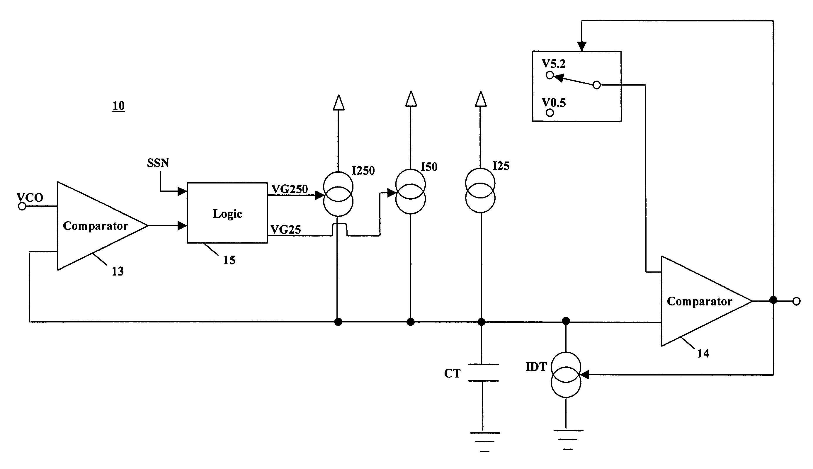
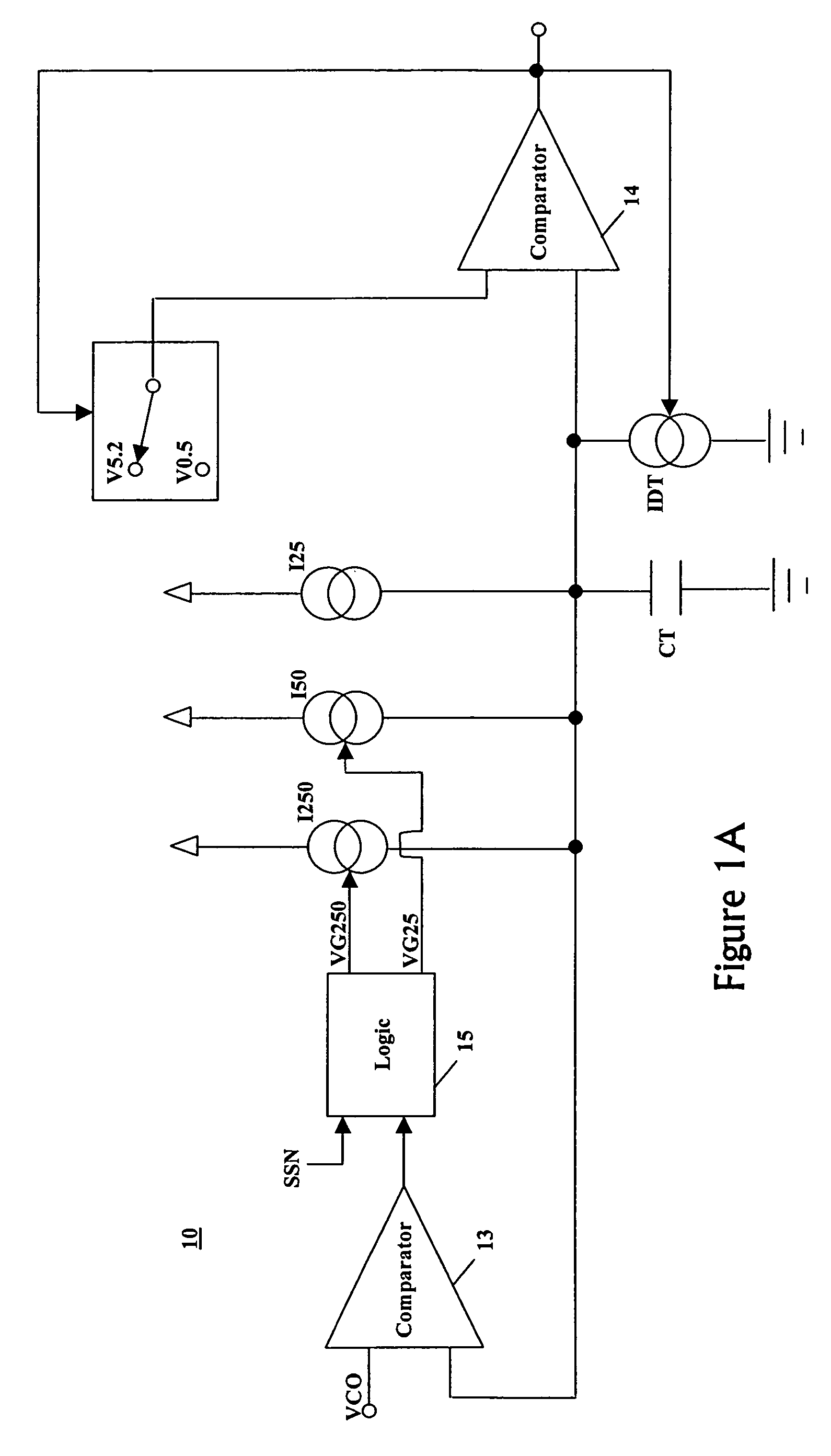
[0020]The present invention provides a dual slope dual range on chip oscillator that can be operated in a number of ranges to provide flexibility for various oscillator applications. The present invention is particularly useful in several applications, including lighting, power supplies, resonance circuits generally, or where PWM switching is used. By providing a dual slope, dual range oscillator, ranges of operations for oscillator applications can be modified in real time to provide a wider range of operation for the integrated circuit oscillator, as well as greater flexibility for oscillator applications.

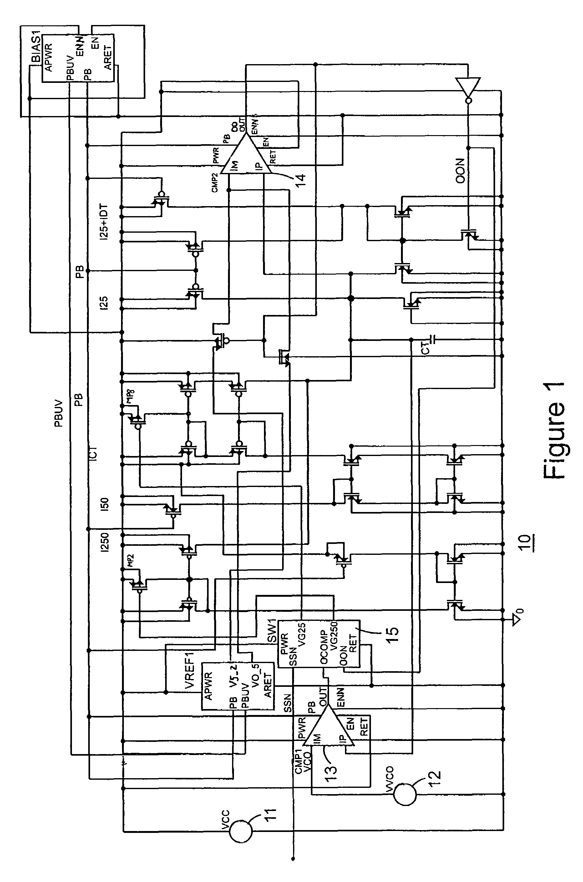
[0021]Referring now to FIG. 1, a schematic diagram of an embodiment according to the present invention is shown generally as circuit 10. FIG. 1A shows a simplified schematic diagram of circuit 10. Circuit 10 includes several representative inputs including a power VCC input 11 and a control voltage VVCO input 12. A comparator 13 receives voltage VVCO input 12 and determines when ...


PUM


Abstract

A dual range oscillator provides two different ranges of oscillator frequency output based on switched current sources charging a capacitor. As several current sources are combined to charge capacitor, the interval for charging the capacitor decreases and changes the oscillator frequency output accordingly. A reference voltage supplied to a comparator checks the voltage on the capacitor to determine when to combine current sources to charge the capacitor and modify the timing interval and the corresponding oscillator frequency output. The different current sources are switched to the capacitor to provide modified charging slopes. The dual slope, dual range oscillator permits frequency switching operation in a variety of environments and applications with a simplified control and integration into a single chip.

Description

RELATED APPLICATION[0001]The present application is based on and claims benefit of U.S. Provisional Application No. 60 / 426,225, filed Nov. 14, 2002, entitled a Dual Slope Dual Range On Chip Oscillator, to which a claim of priority is hereby made.BACKGROUND OF THE INVENTION[0002]1. Field of the Invention[0003]The present invention relates generally to a controlled oscillator, and relates more particularly to a multiple range oscillator with selectable inputs for range selection.[0004]2. Description of the Related Art[0005]Oscillators, and especially on chip oscillators, are used in numerous applications involving integrated circuit products, for example. In particular, saw tooth oscillators are used in many applications and are traditionally implemented by providing a current source that charges a capacitor. The capacitor is charged and discharged to produce an oscillating output. Voltage controlled oscillators also provide an oscillator output based on a control voltage to determine...

Claims


Application Information

Patent Timeline
Patent Type & Authority Patents(United States)
IPC IPC(8): H03K3/02H03B5/24H03K3/26H03K3/0231
CPCH03K3/0231
Inventor RUSU, IULIARIBARICH, THOMAS
Owner INFINEON TECH AMERICAS CORP
Why Eureka
Try Eureka