Duplexer using surface acoustic wave filters

Active Publication Date: 2006-05-30
TAIYO YUDEN KK
View PDF28 Cites 43 Cited by
  • Summary
  • Abstract
  • Description
  • Claims
  • Application Information

AI Technical Summary

Benefits of technology

[0011]It is an object of the present invention to provide

Problems solved by technology

The dielectric type duplexer has a relatively large size and has difficulty in downsizing and thinning the portable terminal equipment.
However, these proposals are silent in how to reduce the influence of one filter cha

Method used


Image

  • Duplexer using surface acoustic wave filters
  • Duplexer using surface acoustic wave filters
  • Duplexer using surface acoustic wave filters

Examples


Embodiment Construction

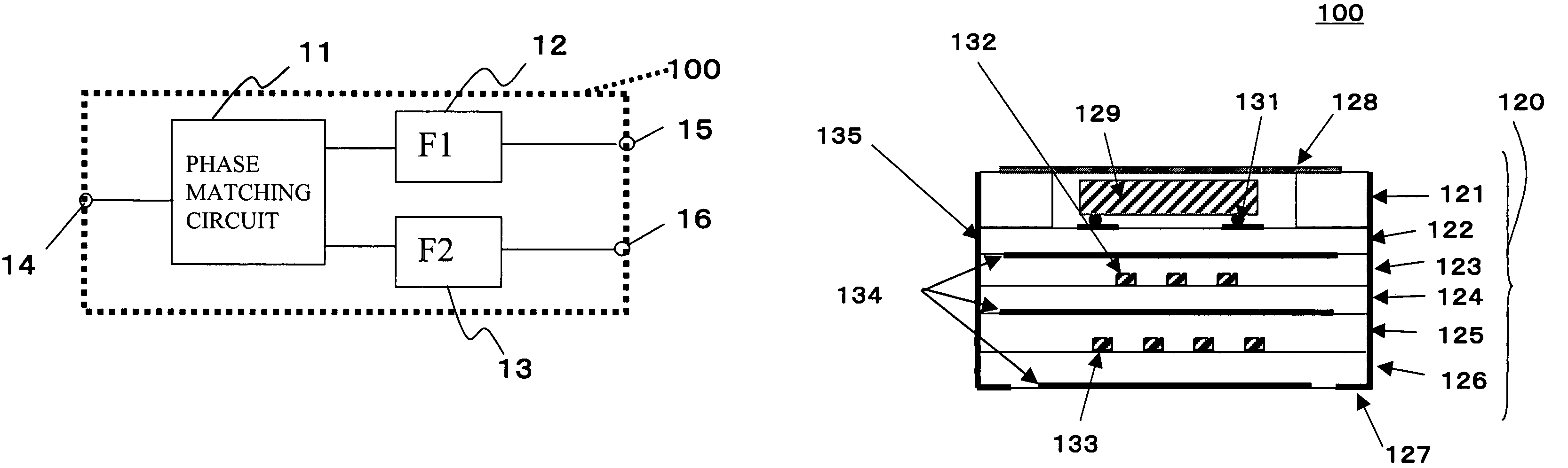
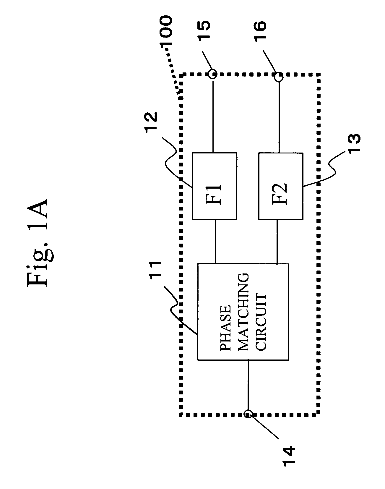
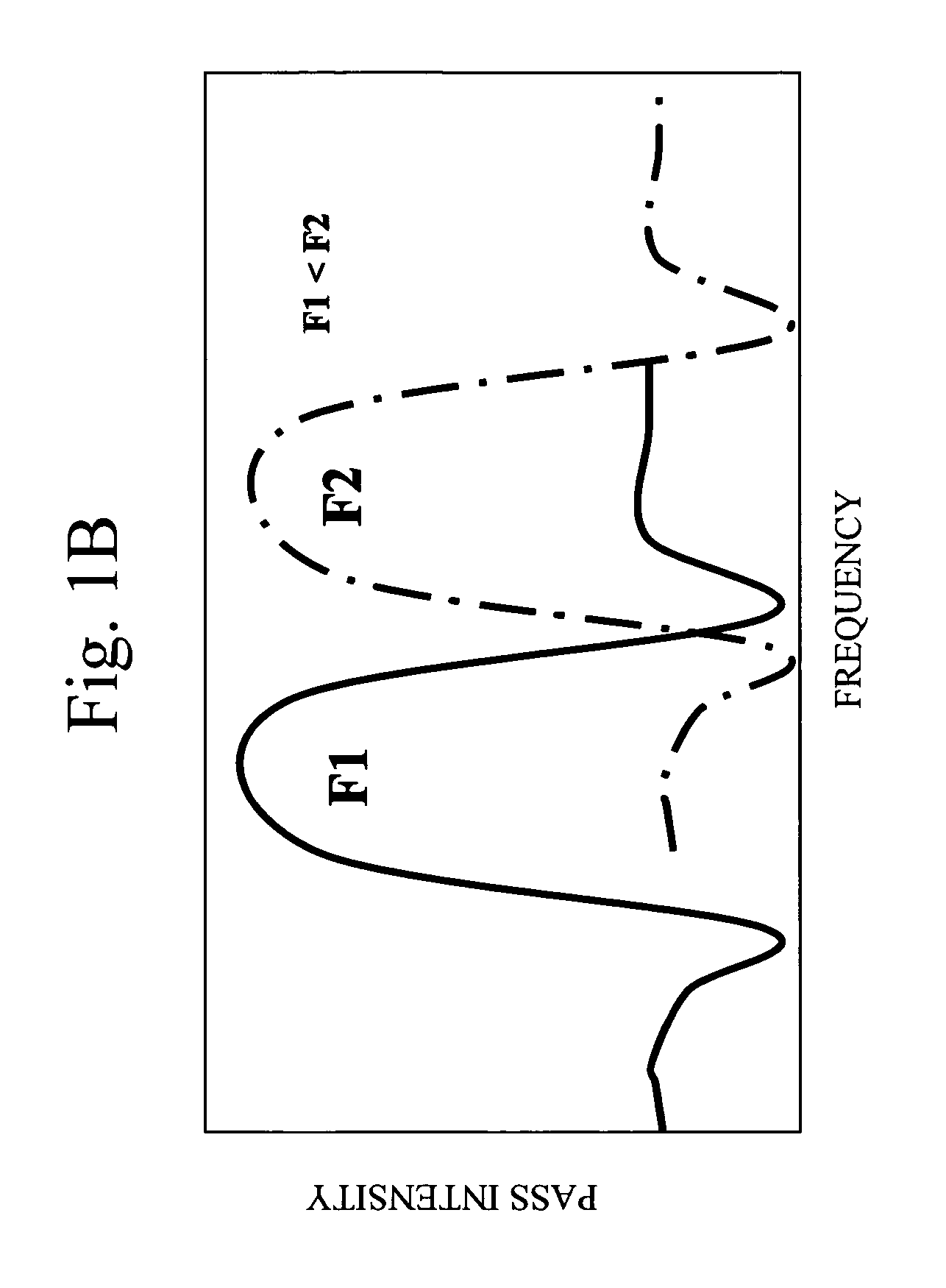
[0037]A description will now be given, with reference to FIGS. 1A and 1B, of the outline of a duplexer according to an embodiment of the present invention. FIG. 1A schematically shows a circuit configuration of a duplexer, and FIG. 1B shows a frequency characteristic of the duplexer. In FIG. 1B, the horizontal axis denotes the frequency that becomes higher as the position on the axis goes rightwards, and the vertical axis denotes the pass intensity that increases as the position on the axis goes upwards.

[0038]Referring to FIG. 1A, a duplexer 100 has two filters 12 (F1) and 13 (F2), a phase matching circuit 11, a common terminal 14, a transmit terminal 15 and a receive terminal 16. The common terminal 14 is used to make a connection with an external circuit that receives and transmits waves via an antenna. The external circuit may be a transmission cable. The transmit terminal 15 is used to make a connection with a transmitter arranged outside of the duplexer 100. A transmit signal f...


PUM


Abstract

A duplexer includes two surface acoustic wave (SAW) filters having different center frequencies, a phase matching circuit that matches phases of the two SAW filters, a package in which the SAW filters and the phase matching circuit are housed, the package having a die-attached layer on which a chip of the SAW filters is facedown mounted, and ground line patterns provided on the die-attached layer and an underlying layer that underlies the die-attached layer, the ground line patterns forming inductances.

Description

BACKGROUND OF THE INVENTION[0001]1. Field of the Invention[0002]The present invention generally relates to a duplexer using surface acoustic wave filters.[0003]2. Description of the Related Art[0004]Recently, cellular phones and portable information equipment have spread widely along with the development of mobile communications systems. It has been considerable activity in downsizing and improving the terminal equipment among many manufacturers. Some cellular phones deal with both the analog and digital systems and employ a variety of frequency bands such as the 800 MHz–1 GHz band and 1.5 GHz–2.0 GHz band.[0005]The recent development of cellular phones is directed to expanding the terminal functions that follow diversified system specifications. For instance, there are dual-mode cellular phones having the analog and digital systems, and dual-frequency cellular phones conforming to TDMA (Time Division Multiple Access) and CDMA (Code Division Multiple Access). There are also dual-ban...

Claims


Application Information

Patent Timeline
IPC IPC(8): H03H9/72H03H9/64H03H9/10H03H9/25H04B1/52
CPCH03H9/0576H03H9/6483H03H9/72H03H9/725H04B1/52
Inventor IWAMOTO, YASUHIDEMATSUDA, TAKASHI
Owner TAIYO YUDEN KK
Why Eureka
Try Eureka