Paraxial cloak design and device

a technology of paraxial cloaks and cloaks, applied in camouflage devices, optical elements, instruments, etc., can solve the problems of unidirectional incident light schemes, difficult experimentation realization of such transformational optics, and non-unity magnification, etc., and achieve the effect of reducing aberrations

Active Publication Date: 2016-01-28
UNIVERSITY OF ROCHESTER
View PDF6 Cites 36 Cited by
  • Summary
  • Abstract
  • Description
  • Claims
  • Application Information

AI Technical Summary

Benefits of technology

[0007]Paraxial cloaking devices and related methods, as described herein, provide a cloaking volume by which an object can be hidden from view relative to a continuous range of viewing directions. The cloaking devices described herein can be constructed with readily available off-the-shelf isotropic optical components, such as lenses and mirrors, thereby negating the need for any artificial electric and / or magnetic materials (i.e., metamaterials) in at least some implementations. Such devices have potential usages in many different fields, for example, in secure communications, transportation, military applications, and medical devices.
[0013]As another example, a paraxial cloaking device can be rotationally symmetric and includes three or more lenses. For example, a rotationally symmetric cloaking device can include three or more lenses that are centered on the reference optical axis. As another example, a rotationally symmetric cloaking device can include four or more lenses that are centered on the reference optical axis. At least one of the lenses can include an achromatic doublet to reduce aberrations.

Problems solved by technology

Experimental realization of such transformational optics has been difficult, due to the previously perceived need for artificial electric and magnetic materials (called ‘metamaterials’), the narrow-band spectrum involved, infinite phase velocity (or negative index to compensate this), and anisotropy in the theory (Gbur, G. Invisibility physics: Past, present, and future.
Yet, these schemes work only for unidirectional incident light, as they are not designed for continuous multidirectional cloaking, and can have non-unity magnifications.
Despite the advances in cloaking, a 3-D multidirectional cloak has been elusive.

Method used


Image

  • Paraxial cloak design and device
  • Paraxial cloak design and device
  • Paraxial cloak design and device

Examples


example three

Lens Cloak Parameters

[0112]For the first and last lenses (1 and 3) 200 mm focal length, BK7, 75 mm diameter lenses were used. For the center lens, two −100 mm focal length, BK7, 50 mm diameter lenses were used, back-to-back, to create a lens with focal length of approximately −50 mm. All lenses were catalogue optics from Edmund Optics. From equation (24), t1=t2 equals approximately 100 mm was obtained. Including the lens thicknesses and the material indices of refraction, t1 was optimized slightly so that the afocal condition C=0 was closely achieved. Diameter of last lens needs to be >150 mm for all rays to pass (no “vignetting”). For the CODE V simulation, the apertures were not restricted to the actual lens sizes. The aperture stop was the first surface. Aperture diameter sizes (for no vignetting) of the first and second diverging lenses in the center are 54 mm and 61 mm, respectively. Total length of the system is 219 mm.

Example Four Lens Cloak

[0113]A four lens ‘ideal’ paraxial ...

example four

Lens Cloak Parameters

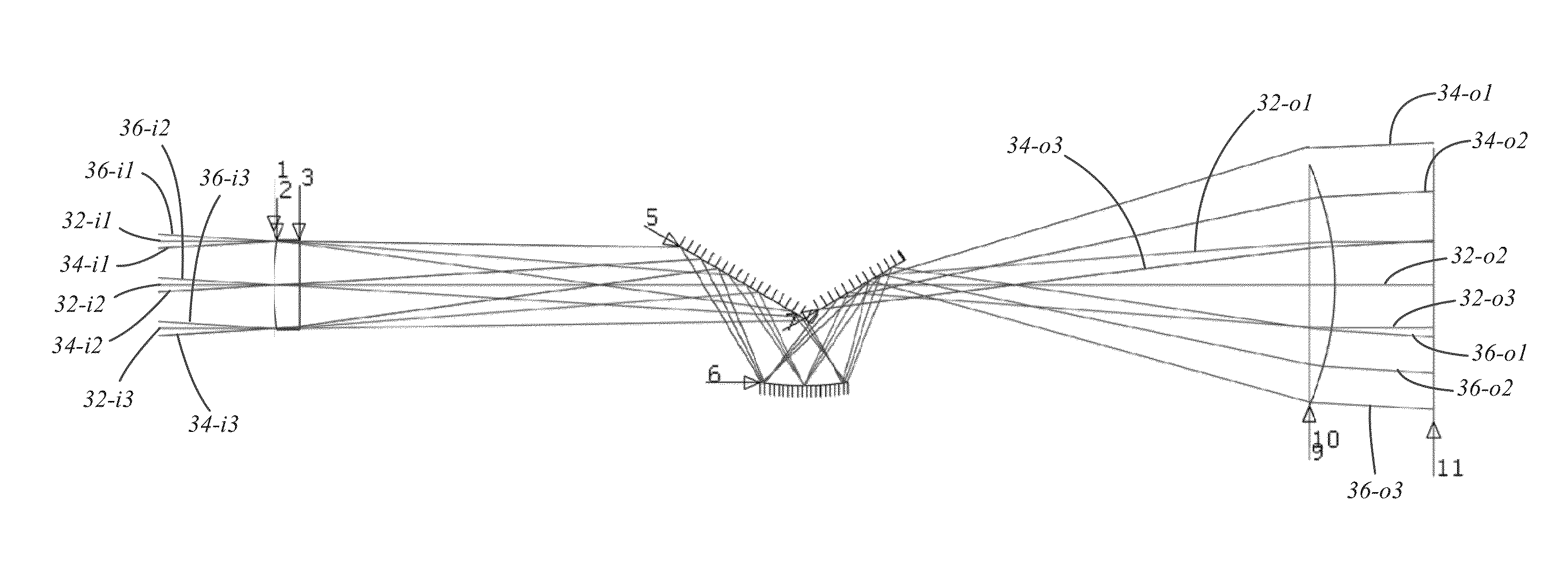
[0116]For the first and last lenses (1 and 4), 200 mm focal length, 50 mm diameter achromatic doublets composed of BK7 and SF2 glasses were used. For the center two lenses (2 and 3), 75 mm focal length, 50 mm diameter achromatic doublets composed of SF11 and BAF11 glasses were used. All doublets were off-the-shelf catalogue optics from Thorlabs and had antireflection coating in the visible spectrum. For the CODE V simulations, the aperture sizes were not restricted, so as to ensure no vignetting. The aperture stop was the first surface. Diameters of the second, third, and last doublets need to be >33 mm, 51 mm, and 112 mm, respectively, for no vignetting. Total length of the system is 910 mm.

[0117]Extending Paraxial Cloaking to Include the Full Field

[0118]We now discuss non-limiting examples of paraxial cloaks that work for the full-field (matched amplitude and phase). FIG. 32 schematically shows one example of a full field paraxial cloak. In FIG. 32, the image ...


PUM


Abstract

A paraxial cloaking device provides a cloaking volume in which an item can be hid from view. A cloaking device includes an optical input receiving light rays and an optical output from which a continuous range of directions of the received light rays exit the paraxial cloaking device. The cloaking volume being disposed between the optical input and the optical output. For received light rays having incoming directions non-parallel to the reference optical axis up to a first angle, each of the received light rays exits the cloaking device substantially aligned with the respective received light ray and does not pass through the cloaking volume. The paraxial cloaking device has a unity magnification factor. In some instances, the paraxial cloaking device includes a phase matching element.

Description

CROSS-REFERENCE TO RELATED APPLICATIONS[0001]This patent application claims priority to U.S. application Ser. No. 62 / 028,658 filed on Jul. 24, 2014 for a “Paraxial Cloak Design and Device,” the entire content of which is hereby incorporated by this reference.STATEMENT AS TO RIGHTS TO INVENTIONS MADE UNDER FEDERALLY SPONSORED RESEARCH AND DEVELOPMENT[0002]This work was supported by the Army Research Office Grant No. W911 NF-12-1-0263 and the DARPA DSO Grant No. W31P4Q-12-1-0015. The government has certain rights in the invention.BACKGROUND[0003]Optical spatial cloaking has captured the imagination of both the popular culture and scientific communities (see, e.g., Gbur, G. Invisibility physics: Past, present, and future. Progress in Optics 58, 65-114 (2013)). Seminal works in optical spatial cloaking includes work by Leonhardt (Leonhardt, U. Optical conformal mapping. Science 312, 1777-1780 (2006)) and Pendry, Schurig, and Smith (Pendry, J. B., Schurig, D. & Smith, D. R. Controlling e...

Claims


Application Information

Patent Timeline
Patent Type & Authority Applications(United States)
IPC IPC(8): G02B17/00G02B1/00G02B17/08G02B27/00G06F17/16
CPCG02B17/008G02B1/007G06F17/16G02B27/0012G02B17/08F41H3/00G06F30/00
Inventor CHOI, JOSEPH S.HOWELL, JOHN C.
Owner UNIVERSITY OF ROCHESTER
Why Eureka
Try Eureka