Optically polarizing retardation arrangement, and microlithography projection exposure machine

a retardation arrangement and retardation technology, applied in the direction of polarizing elements, printing, instruments, etc., can solve the problems of antireflection coatings and reflective coatings (mirror coatings) that can unfavorably alter the polarization state of radiation

Inactive Publication Date: 2006-05-30
CARL ZEISS SMT GMBH
View PDF25 Cites 19 Cited by
  • Summary
  • Abstract
  • Description
  • Claims
  • Application Information

AI Technical Summary

Benefits of technology

[0038]In one embodiment, the retardation arrangement has a substrate and a reflective coating which is applied to the substrate, which is effective for radiation from the extreme ultraviolet (EUV) region, and which has a locally different polarization-varying reflective effect for the purpose of forming retardation zones with a different retardation effect. The reflective coating can be designed as a multilayer reflective coating having layers, lying one above another, of suitable material (for example molybdenum and silicon).
[0039]The multilayer reflective coating can be constructed in the vicinity of the mirror substrate like a conventional EUV multilayer mirror. In order to generate a polarization-dependent phase transmission, it is possible to provide on this layer arrangement a grating arrangement of narrow structures running next to one another at a spacing which are likewise constructed in an inherently multilayer fashion and, for example, continue the layer sequence of the mirror situated therebelow. At least in some regions, the grating structure can be periodic with a period length of the order of magnitude of the radiation wavelength, but preferably being shorter than the radiation wavelength (sub-λ structures). It is possible thereby to generate a birefringence effect similar to the structure-induced birefringence known from transparent optical components (shape birefringence). The arrangement of the diffractive structural elements, that is to say, in particular, their alignment, their periodicity spacing and / or the structural depth can vary locally in order to form retardation zones of different retardation effect.

Problems solved by technology

Likewise, antireflection coatings and reflective coatings (mirror coatings) can unfavourably alter the polarization state of the radiation such that, for example, a linear polarization state at the input of the illumination system is converted into an undefined elliptic polarization state at the exit of the projection objective.

Method used


Image

  • Optically polarizing retardation arrangement, and microlithography projection exposure machine
  • Optically polarizing retardation arrangement, and microlithography projection exposure machine
  • Optically polarizing retardation arrangement, and microlithography projection exposure machine

Examples


Embodiment Construction

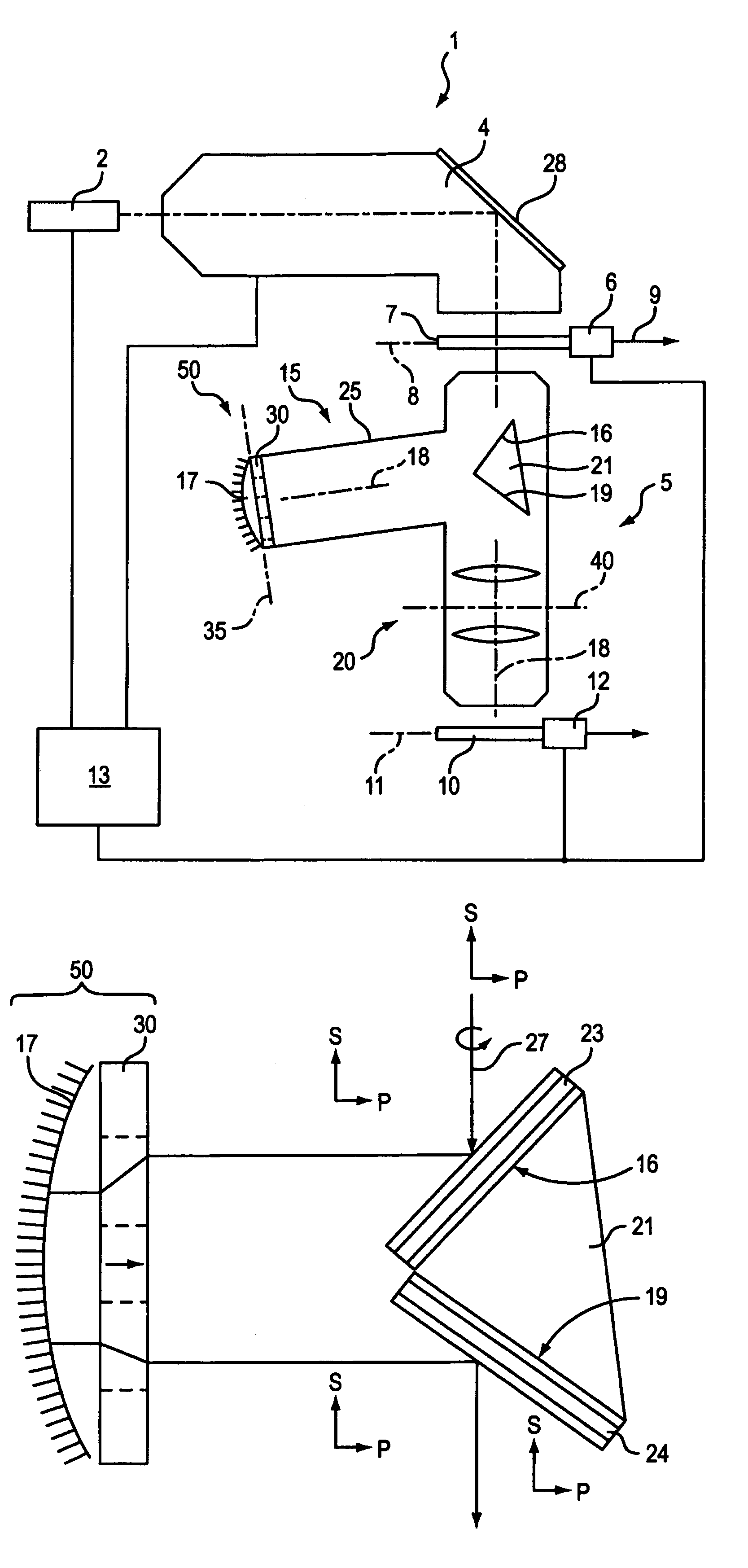
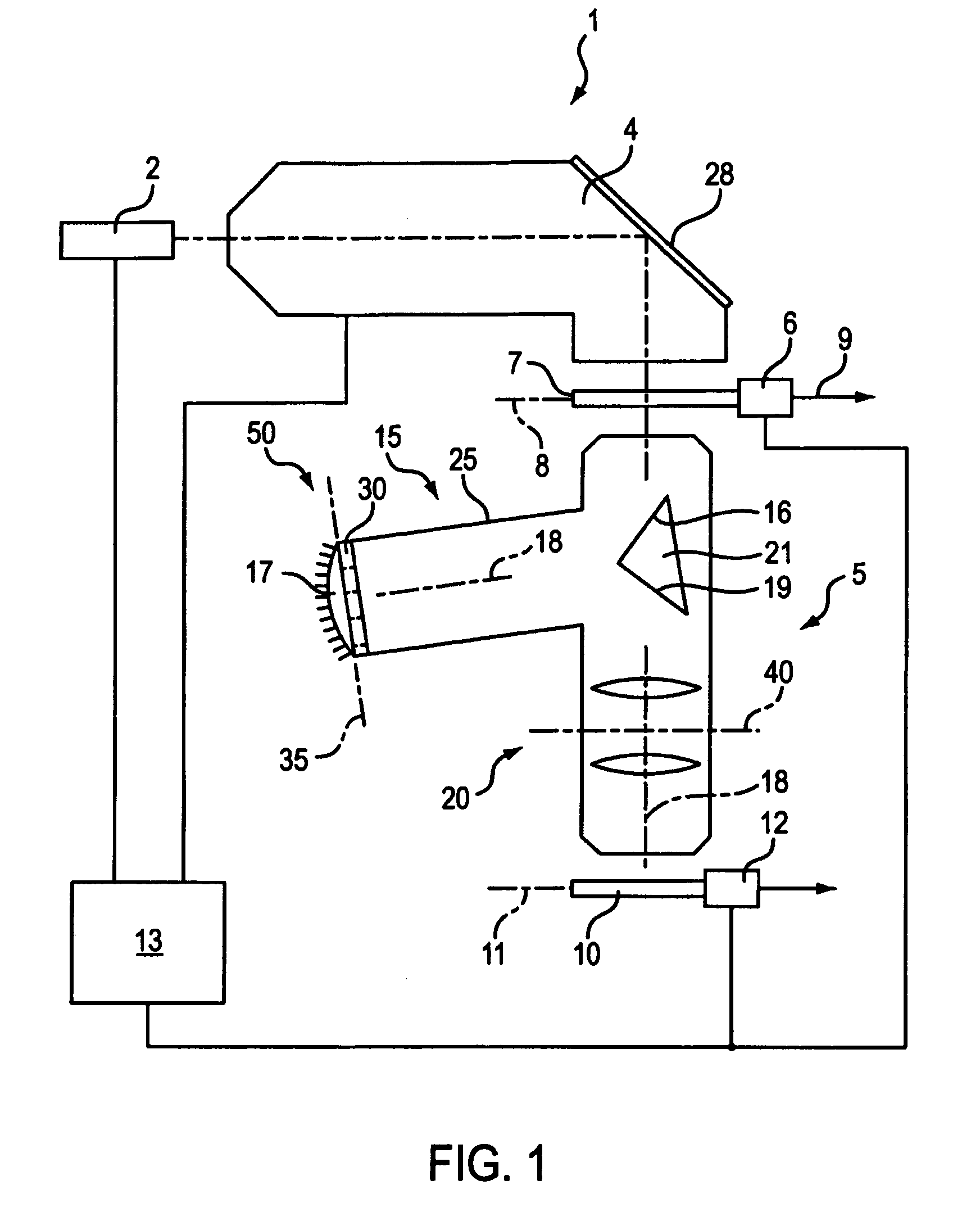
[0056]A microlithography projection exposure machine in the form of a wafer stepper 1 which is provided for producing semiconductor components of large-scale integration is shown diagrammatically in FIG. 1. The projection exposure machine comprises as light source an excimer laser 2 which emits ultraviolet light with an operating wavelength λ of 157 nm and which, in the case of other embodiments, can also lie thereabove, for example at 193 nm or 248 nm, or therebelow. A downstream illuminating system 4 generates a large, sharply delimited and homogeneously illuminated image field which is adapted to the telecentricity requirements of the downstream projection objective 5. The illuminating system has devices for selecting the illumination mode and can, for example, be switched between conventional illumination with a variable degree of coherence, angular field illumination and dipole or quadrupole illumination.

[0057]A device 6 for holding and manipulating a mask 7 is arranged behind ...


PUM

PropertyMeasurementUnit
axial thicknessaaaaaaaaaa
angle of inclinationaaaaaaaaaa

Abstract

A retardation arrangement for converting an input radiation beam, incident from an input side of the retardation arrangement, into an output radiation beam which has over its cross section a spatial distribution of polarization states which can be influenced by the retardation arrangement and differs from the spatial distribution of polarization states of the input radiation, is designed as a reflective retardation arrangement. A useful cross section of the retardation arrangement has a multiplicity of retardation zones of different retardation effect. Such a mirror arrangement having a retardation effect varying as a function of location can be used to compensate undesired fluctuations in the polarization state over the cross section of an input radiation beam and/or to set specific output polarization states, for example in order to set radial or tangential polarization.

Description

[0001]This is a continuation-in-part application pending prior application Ser. No. 10 / 151,867 filed May 22, 2002 now U.S. Pat. No. 6,856,379, of Karl-Heinz SCHUSTER entitled POLARIZER AND MICROLITHOGRAPHY PROJECTION SYSTEM WITH A POLARIZER, which, in turn, claims priority from German Patent Application No. 101 24 803.2, filed on May 22 2001.BACKGROUND OF THE INVENTION[0002]1. Field of the Invention[0003]The invention relates to a retardation arrangement for converting an input radiation beam, incident from an input side of the retardation arrangement, into an output radiation beam which has over its cross section a spatial distribution of polarization states which can be influenced by the retardation arrangement and differs from the spatial distribution of polarization states of the input radiation beam, and to a microlithography projection exposure machine having at least one such retardation arrangement.[0004]2. Description of the Prior Art Used[0005]In order to increase the imag...

Claims


Application Information

Patent Timeline
Patent Type & Authority Patents(United States)
IPC IPC(8): G03B27/72G03B27/28G02B5/18G02B5/30G02B27/28G03F7/20
CPCG02B5/1809G02B5/3083G03F7/70566G03F7/70308G02B27/286G02B5/30G02B27/28G03B27/28G03F7/20
Inventor TOTZECK, MICHAELENKISCH, BIRGITSCHUSTER, KARL-HEINZ
Owner CARL ZEISS SMT GMBH
Why Eureka
Try Eureka