Magnetic head and magnetic storage apparatus

a magnetic storage and head technology, applied in the direction of head with metal sheet cores, instruments, erasing methods, etc., can solve the problems of material not favorable to the conventional main, material disappearance, and the thickness of the recording layer is necessary to reduce the thickness of the recording layer, so as to prevent the effect of “erasure after recording

Inactive Publication Date: 2006-05-30
HITACHI GLOBAL STORAGE TECH JAPAN LTD
View PDF5 Cites 9 Cited by
  • Summary
  • Abstract
  • Description
  • Claims
  • Application Information

AI Technical Summary

Benefits of technology

[0008]The present invention was completed in view of the foregoing. It is an object of the present invention to provide a magnetic head for perpendicular magnetic recording which prevents “erasure after recording” and has a magnetic field strength and a magnetic field distribution both suitable for the narrow track width.
[0010]According to the present invention, the recording magnetic pole consists of the main magnetic pole which is short in the direction of the flying surface and the yoke which is wider in the track width direction than the main magnetic pole. This separate structure prevents the magnetic pole from magnetizing in the direction of the flying surface unlike the conventional one which elongates in the depthwise direction from the flying surface. In addition, the main magnetic pole is made of a material having a positive magnetostriction constant and a high saturation magnetic flux density. The yoke is made of a material having a negative magnetostriction constant, so that it causes the main magnetic pole to magnetize in the direction parallel to the surface of the recording medium and prevents erasure after recording.
[0011]According to the present invention, the main magnetic pole should be patterned as follows so that it increases in the recording magnetic field strength without causing erasure after recording.

Problems solved by technology

The disadvantage of increasing the recording density in conventional longitudinal recording is that it is necessary to reduce the thickness of the recording layer because the demagnetizing field reaches a maximum in the written magnetization transition region on the recording medium.
The result is that recorded data disappear due to thermal scattering.
However, because of its large magnetostriction, such a material is not favorable to the conventional main magnetic pole elongating in the depthwise direction from the flying surface.

Method used


Image

  • Magnetic head and magnetic storage apparatus
  • Magnetic head and magnetic storage apparatus
  • Magnetic head and magnetic storage apparatus

Examples


example 1

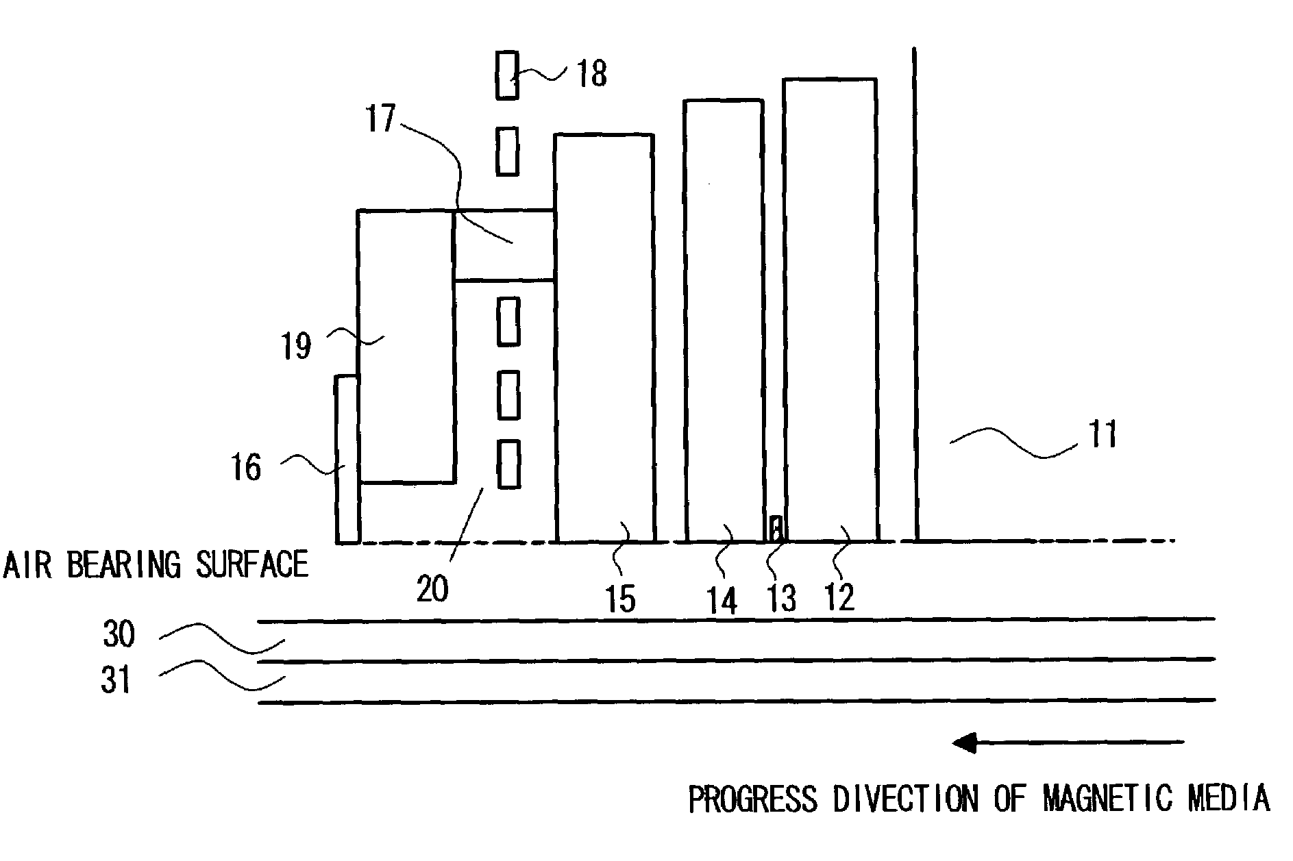
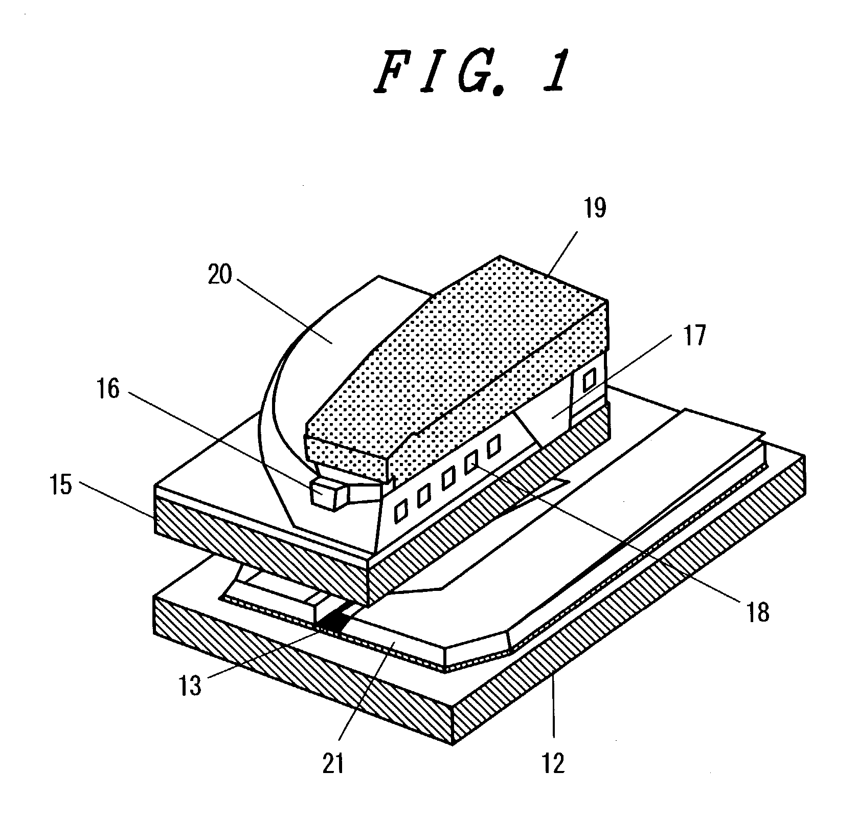
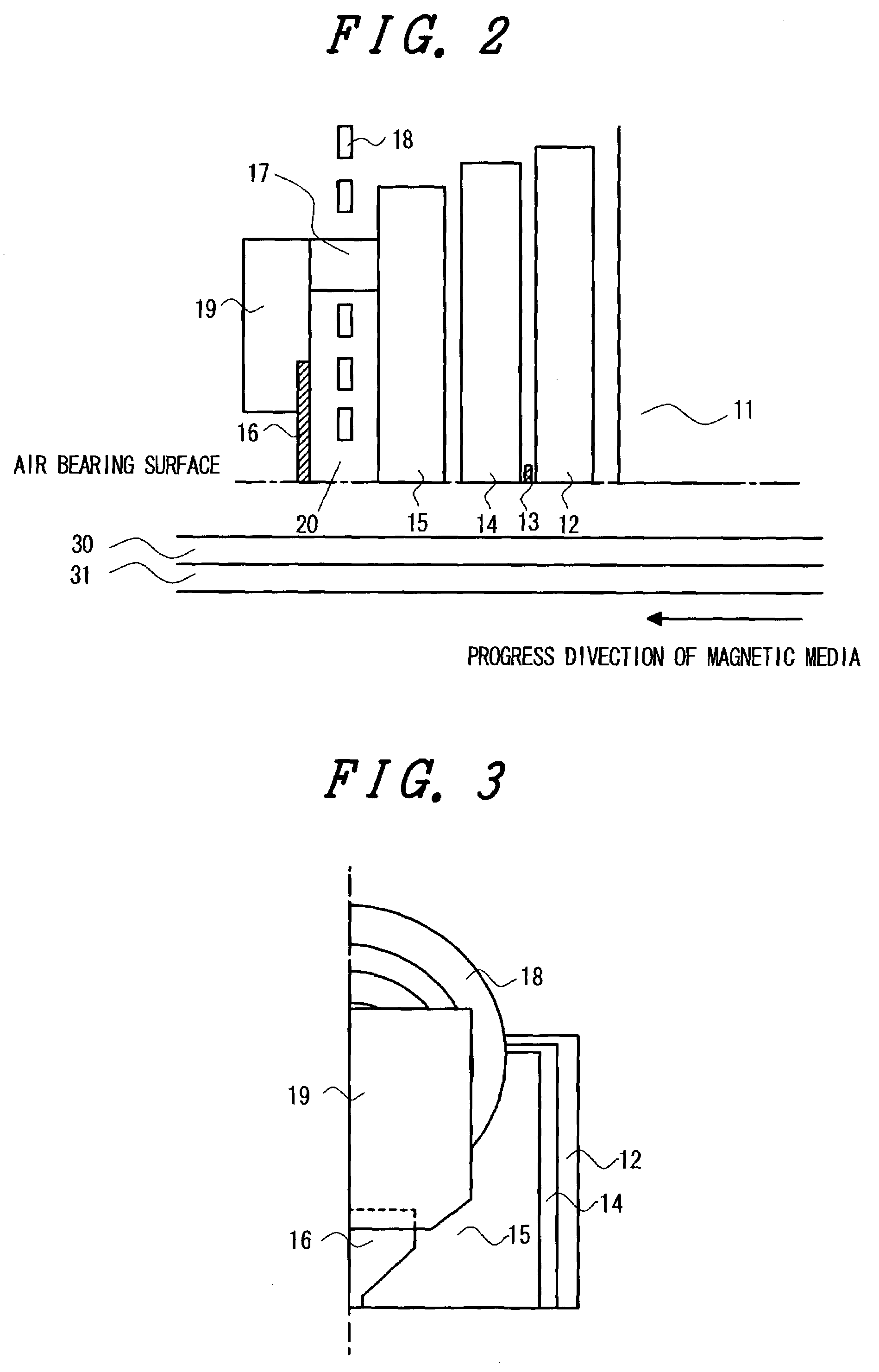
[0036]This example demonstrates the magnetic head for perpendicular recording (to be simply referred to as the magnetic head hereinafter) whose structure is shown in FIGS. 1 to 3. FIG. 1 is a sectional perspective view of the magnetic head in which the recording head and the reproducing head are separated from each other, with the recording head being the perpendicular head manufactured according to the present invention. FIG. 2 is a sectional view perpendicular to the air bearing surface and the substrate surface. FIG. 3 is a plan view showing the structure of the magnetic head (right half). This plan view is parallel to the air bearing surface and the substrate surface.

[0037]In FIGS. 1 to 3, there are shown a substrate 11, a lower shield 13, a magnetoresistive film 13, an upper shield 14, a secondary magnetic pole 15, a main magnetic pole 16, a back yoke 17, a coil 18, and a yoke 19 attached to the main magnetic pole. Thus, the magnetic head in this example is constructed such tha...

example 2

[0046]This example demonstrates the magnetic head whose structure is shown in FIGS. 6 and 7. FIG. 6 is a sectional view perpendicular to the air bearing surface and the substrate surface. FIG. 7 is a plan view showing the structure of the magnetic head (right half). This plan view is perpendicular to the air bearing surface and the substrate surface. The magnetic head in this example differs from the one shown in FIG. 2 in that the main magnetic pole is formed at the trailing side of the yoke. This structure facilitates connection between the main magnetic pole and the yoke. Moreover, the magnetic head in this example is characterized in that there exists the following relationship among the saturation magnetic flux density Bs(P1) of the material contained in the main magnetic pole 16, the saturation magnetic flux density Bs(P2) of the material constituting the yoke 19, the average film thickness t1 of the magnetic body constituting the main magnetic pole 16, and the average film th...

example 3

[0049]This example demonstrates the magnetic head whose structure is shown in FIG. 9. FIG. 9 is a sectional view perpendicular to the air bearing surface and the substrate surface. The magnetic head in this example is characterized in that the main magnetic pole 16 and the yoke 19 are formed between the secondary magnetic pole 15 and the upper shield and the main magnetic pole is close to the trailing side of the yoke. Arranging the main magnetic pole, secondary magnetic pole, and yoke in this manner makes the recording magnetic pole and the reproducing magnetic pole close to each other, thereby improving the characteristic properties of the head.

[0050]After the reproducing element has been formed, the yoke 19 is formed (with the gap film attached thereto) by electroplating in the same way as in Example 1. Electroplating is followed by CMP for planarization. A 0.2 μm thick film is formed from CoNiFe or FeCo having a Bs larger than 2.0 T. The main magnetic pole in a desired shape is ...


PUM

PropertyMeasurementUnit
saturation magnetic flux densityaaaaaaaaaa
thickaaaaaaaaaa
thickaaaaaaaaaa

Abstract

Disclosed herein is a magnetic head for perpendicular recording in which the main magnetic pole has reduced remanent magnetization and is less liable to cause erasure after recording. These characteristic properties were realized by constructing the magnetic head such that the recording magnetic pole and the yoke are separate from each other and the main magnetic pole is formed from a material with a high saturation magnetic flux density and the yoke is formed from a material having a negative magnetostriction constant.

Description

BACKGROUND OF THE INVENTION[0001]1. Field of the Invention[0002]The present invention relates to a magnetic head and a magnetic storage apparatus for perpendicular magnetic recording.[0003]2. Description of Related Art[0004]There has been an increasing demand for larger capacity and smaller size on the hard disc drive used as external storage for information processing apparatus such as computers. This demand has been met mainly by increasing the recording density of a hard disc. The disadvantage of increasing the recording density in conventional longitudinal recording is that it is necessary to reduce the thickness of the recording layer because the demagnetizing field reaches a maximum in the written magnetization transition region on the recording medium. The result is that recorded data disappear due to thermal scattering. By contrast, it is comparatively easy to increase the recording density for perpendicular recording (in which magnetization for recording takes place in the ...

Claims


Application Information

Patent Timeline
Patent Type & Authority Patents(United States)
IPC IPC(8): G11B5/147G11B5/00G11B5/024G11B5/31G11B5/39G11B5/465
CPCB82Y10/00B82Y25/00G11B5/313G11B5/3156G11B5/3967G11B5/024G11B2005/3996G11B5/465G11B2005/0008G11B2005/0013G11B5/3163
Inventor KUDO, KAZUEKAWATO, YOSHIAKINAKAMOTO, KAZUHIROYOSHIDA, NOBUOETOH, KIMITOSHI
Owner HITACHI GLOBAL STORAGE TECH JAPAN LTD
Why Eureka
Try Eureka