Wireless terminal device

a terminal device and wireless technology, applied in the direction of demodulation, electrical equipment, radio transmission, etc., can solve the problem of not specifically disclosed low-pass filter technology, and achieve the effect of effectively eliminating

Inactive Publication Date: 2006-05-30
MITSUBISHI ELECTRIC CORP
View PDF11 Cites 27 Cited by
  • Summary
  • Abstract
  • Description
  • Claims
  • Application Information

AI Technical Summary

Benefits of technology

[0022]In this wireless terminal device, even when the attenuation characteristics of the first low-pass filter for the radio-frequency range deteriorate, the second low-pass filter can attenuat...

Problems solved by technology

However, this low-pass filt...

Method used


Image

  • Wireless terminal device
  • Wireless terminal device
  • Wireless terminal device

Examples


first embodiment

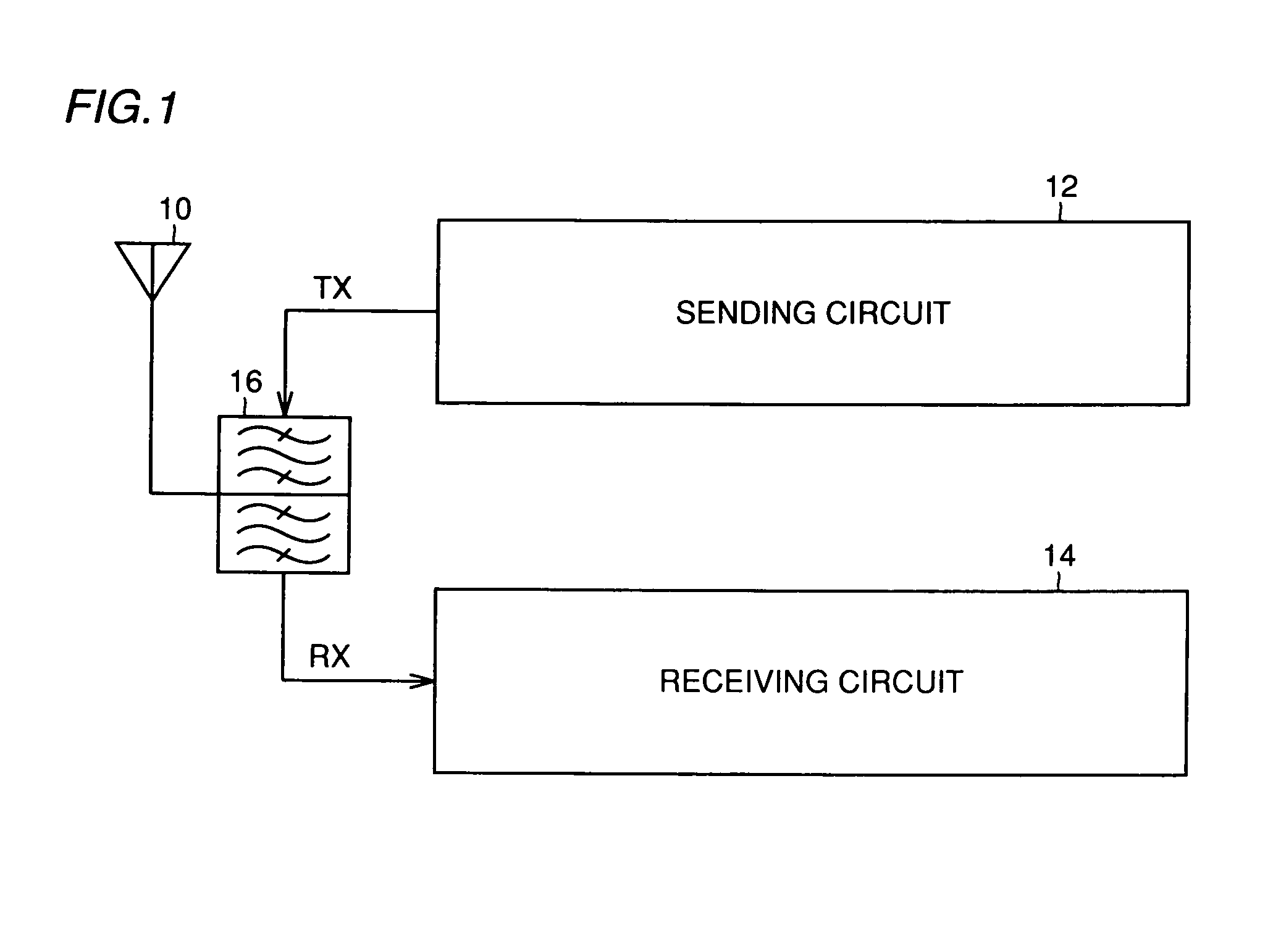
[0044]Referring to FIG. 1, a cellular telephone which is a kind of wireless terminal device includes an antenna 10, a transmitting (sending) circuit 12, a receiving circuit 14 and a transmission / reception branching filter 16.

[0045]This cellular telephone employs a CDMA (Code Division Multiple Access) scheme, and simultaneously performs transmission and reception via single antenna 10. Therefore, the transmitting frequency is different from the receiving frequency and, in this embodiment, is lower than the receiving frequency. Therefore, the transmission / reception branching filter 16 is formed of a band-pass filter passing only a transmitting wave TX therethrough and a band-pass filter passing only a received wave RX therethrough, and hardly passes transmitting wave TX toward receiving circuit 14.

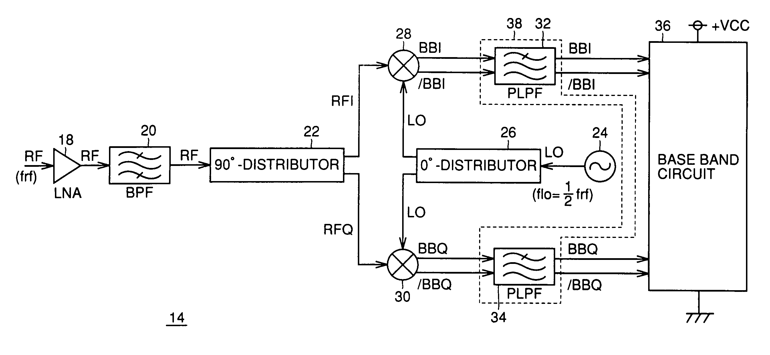
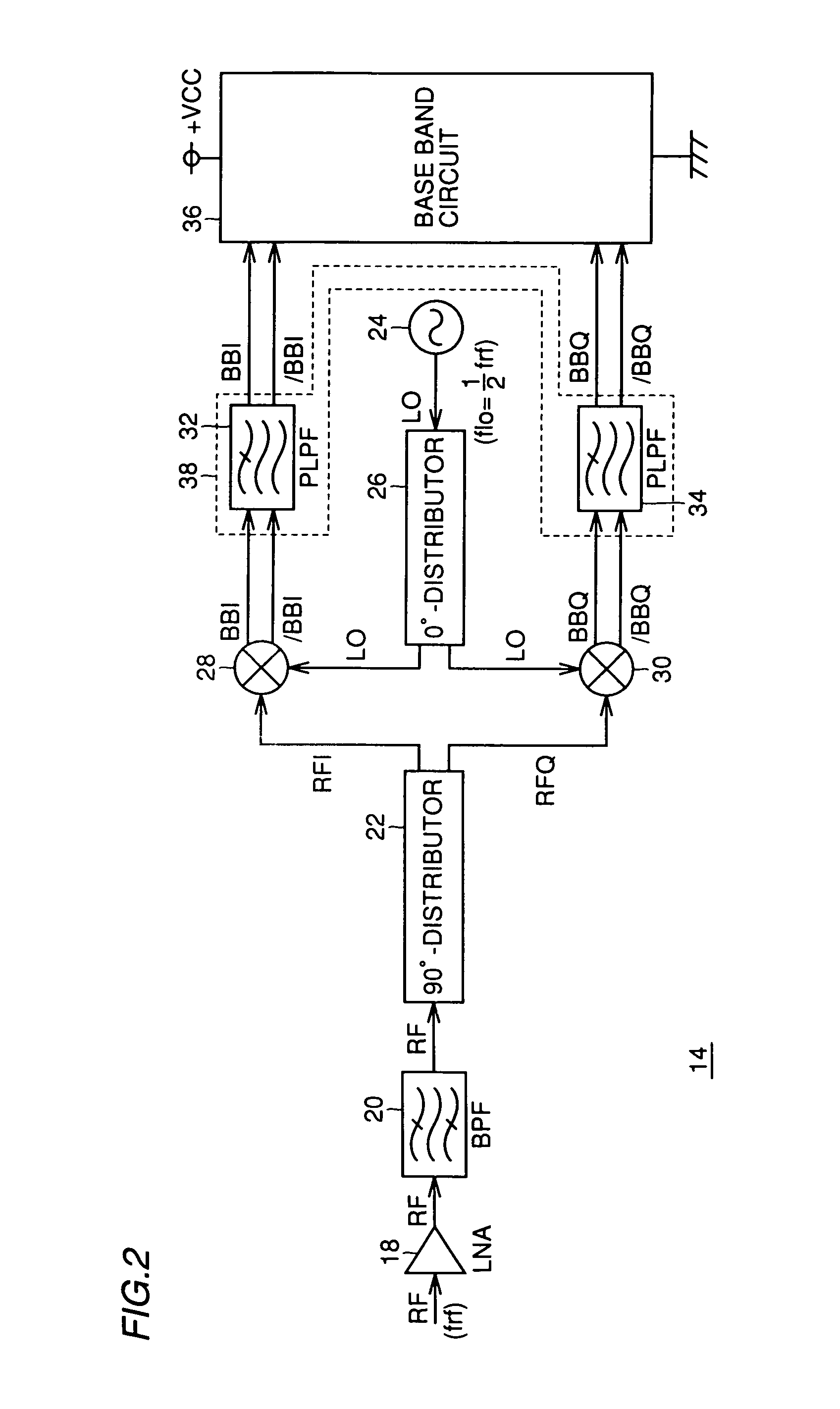
[0046]Referring to FIG. 2, receiving circuit 14 includes a low-noise amplifier (LNA) 18, a band-pass filter (BPF) 20, a 90′-distributor 22, a local oscillator 24, an in-phase 0° distributor ...

second embodiment

Modification of Second Embodiment

[0099]A modification of the second embodiment will now be described in connection with another example of passive low-pass filter PLPF2. As already described, the inductance in passive low-pass filter PLPF2 shown in the second embodiment can have a small inductance value. Therefore, resistance elements may be used instead of the inductances for forming passive low-pass filter PLPF2.

[0100]Referring to FIG. 17, passive low-pass filter PLPF2 according to the modification of the second embodiment includes two resistance elements 425 and 426, and capacitor 423. Resistance element 425 is employed in place of inductor 421 shown in FIG. 13 for passing base band signal BBI (BBQ) sent from passive low-pass filter PLPF1 and transmitting it to base band circuit 36. Likewise, resistance element 426 is employed in place of inductor 422 shown in FIG. 13 for passing base band signal / BBI ( / BBQ) sent from passive low-pass filter PLPF1 and transmitting it to base band...


PUM


Abstract

In a cellular telephone provided with a receiving circuit of a direct conversion type, a passive low-pass filter is arranged between a mixer for an I-channel and a base band circuit for removing interference waves of or above a channel next to a channel neighboring to the I-channel, and another passive low-pass filter is arranged between a mixer for a Q-channel and the base band circuit for removing interference waves of or above a channel next to a channel neighboring to the Q-channel. Since the low-pass filters for removing the interference waves of or above the channel next to the neighboring channel are of a differential type, the circuit scale can be small, and the power consumption is small. Since the interference waves are removed by the passive low-pass filters and the active low-pass filters, only the desired channel can be reliably received.

Description

REFERENCE TO RELATED APPLICATION[0001]This application is a continuation of International Application No. PCT / JP99 / 07396, whose international filing date is Dec. 28, 1999, the disclosure of which is incorporated by reference herein.BACKGROUND OF THE INVENTION[0002]1. Field of the Invention[0003]The present invention relates to a wireless terminal device, and particularly, a wireless terminal device provided with a direct conversion receiving circuit using an orthogonal mixer of a differential type.[0004]2. Description of the Background Art[0005]At present, wireless terminal devices such as a cellular telephone primarily employ heterodyne receiving circuits. Although the heterodyne system requires an intermediate frequency circuit, it can prevent leak of a local oscillation signal to an antenna side because the local oscillation frequency is different from the receive frequency, and therefore can prevent deterioration of sensitivity.[0006]In contrast to this, a direct conversion (hom...

Claims


Application Information

Patent Timeline
IPC IPC(8): H04B1/30H03D7/14
CPCH04B1/30H03D7/1408
Inventor ITOH, KENJINAGANO, HIROAKIKATSURA, TAKATOSHIFUKUYAMA, SHINJIROUMOCHIZUKI, MITSURUMATSUNAMI, YOSHINORISHIMOZAWA, MITSUHIROISHIZU, FUMIOHAYASHI, RYOJI
Owner MITSUBISHI ELECTRIC CORP
Why Eureka
Try Eureka