Antenna arrangement in a mobile station

a mobile station and antenna technology, applied in the direction of resonant antennas, substation equipment, cross-talk/noise/interference reduction, etc., can solve the problems of inability to optimize the antenna efficiency, inability to meet the requirements of mobile station requirements, etc., to achieve optimal electromagnetic compatibility and reduce the disadvantages of prior art solutions

Inactive Publication Date: 2006-05-30
NOKIA TECHNOLOGLES OY
View PDF19 Cites 36 Cited by
  • Summary
  • Abstract
  • Description
  • Claims
  • Application Information

AI Technical Summary

Benefits of technology

[0009]It is an object of the present invention to provide an antenna arrangement with which the disadvantages of prior art solutions would be reduced or avoided. It is especially an object of the present invention that an optimal electromagnetic compatibility would be achieved with an antenna structure and overall assembly that is applicable to large scale mass production of mobile stations.

Problems solved by technology

However, having the antenna inside the housing of the mobile station easily causes interference problems between the antenna and other electronics of the mobile station.
However, while the part of the RF radiation is absorbed with the additional shield, a portion of the RF intensity is lost, which means that the efficiency of the antenna may not be optimal.
This solution, however, is relatively complicated and therefore it is not well suited for mass production.
A further disadvantage with these prior art solutions is their limitation to devices where the antenna is located outside the housing of the mobile station.
If the antenna would be placed inside the housing there could be interference problems between the antenna and other electronics of the device.
It would be possible to use this kind of microstrip antenna inside a mobile station, but there are certain drawbacks related with this prior art solution as well.
Firstly, the dielectric substrate of a microstrip antenna takes a lot of space within the housing of the mobile station, and therefore the size of the housing would become too large, or the space available for other electronics would become too small.
Another drawback is the fact that while the antenna would be located just next to the electronics circuits, the radiation of the antenna could cause RF interference to the electronics.
However, a microstrip antenna tends to cause high radiation intensity in small areas in the nearest surrounding area of the antenna.
A further drawback is related to the fact that it is difficult to connect a microstrip antenna to the RF electronics of a mobile station.
It is quite difficult to arrange these production phases within an automated production line, and thus manual assembly work may be required.

Method used


Image

  • Antenna arrangement in a mobile station
  • Antenna arrangement in a mobile station
  • Antenna arrangement in a mobile station

Examples


Embodiment Construction

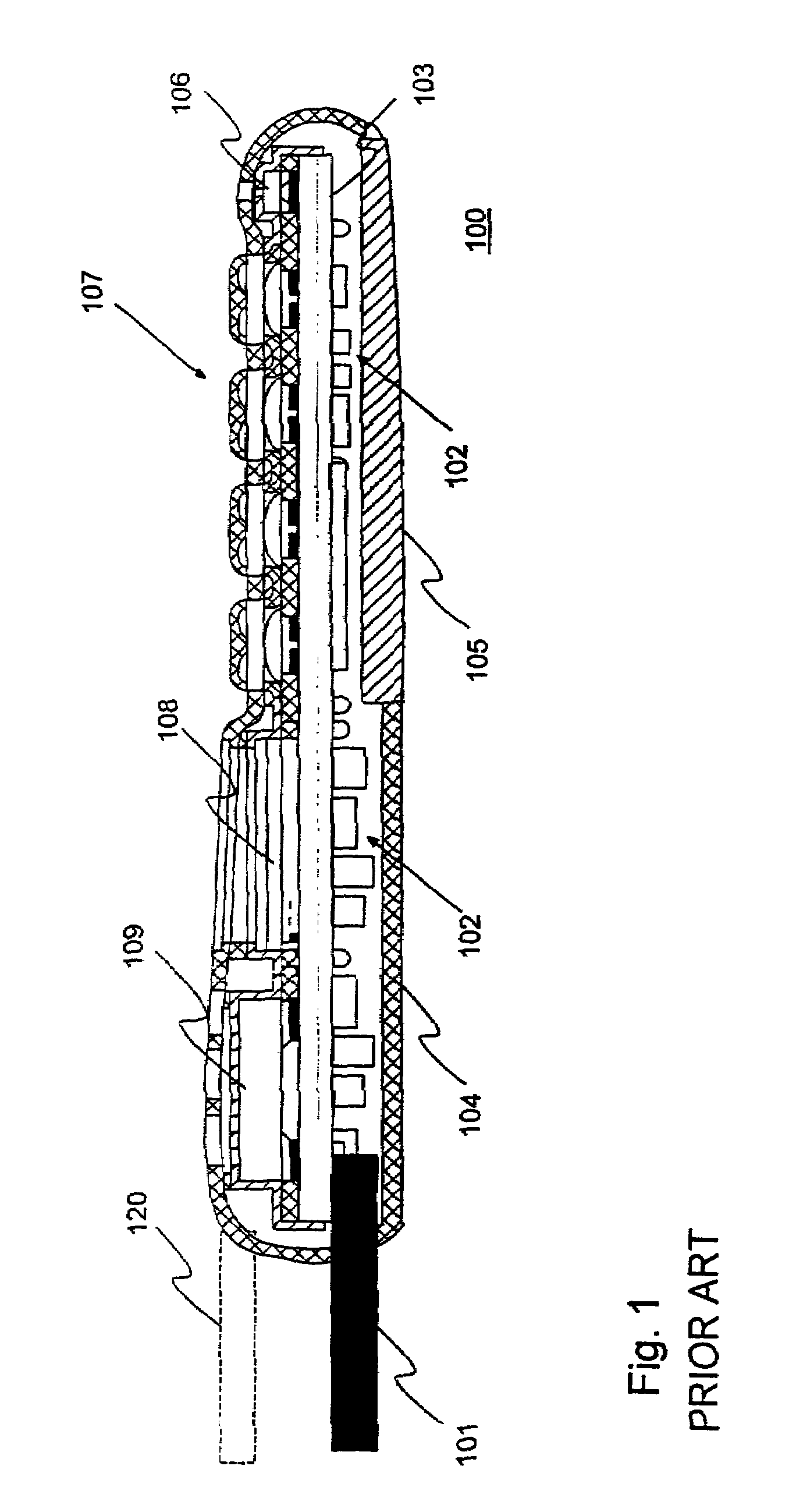
[0032]FIG. 1 was already described in the prior art section above.

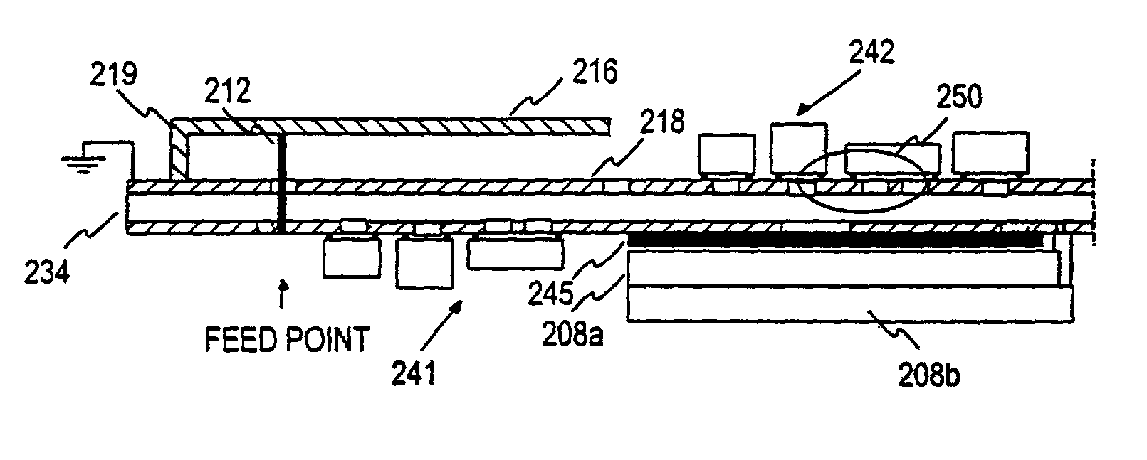
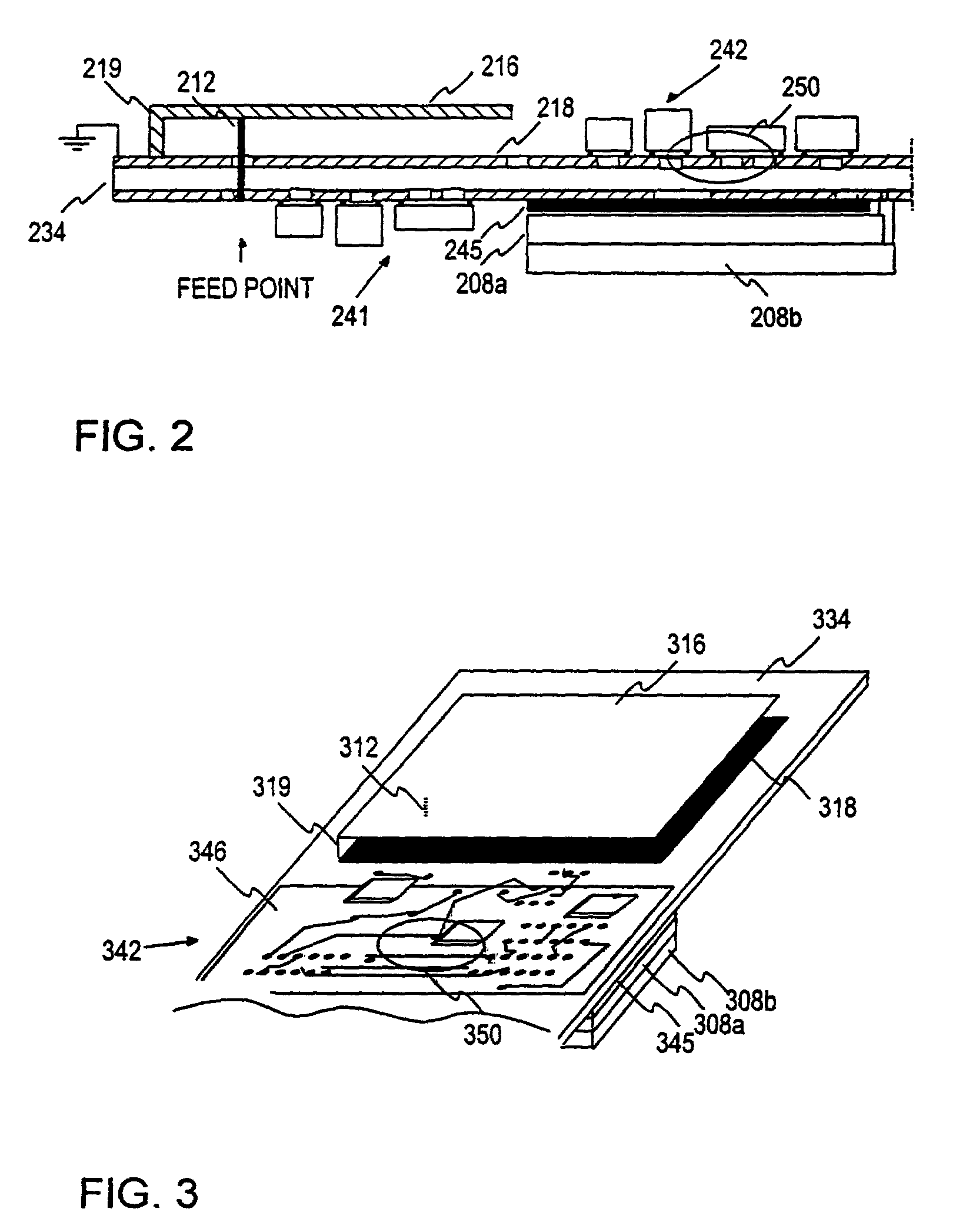
[0033]FIG. 2 illustrates a cross section of an exemplary antenna arrangement according to the present invention. It comprises a ground plane 218 on a printed wired board 234, and a radiator element 216 which is connected to the ground plane from its edge, 219. The radiator element is substantially parallel with the ground plane and the printed wired board, and there is an air gap between the radiator element and the ground plate. The feed point of the radiator element is connected with a pin 212 to a printed wire of the PWB which is further connected to RF circuits 241 such as a duplex filter etc. In this arrangement ground plate and the radiator element of the planar antenna are located at the end of a printed wired board. Further details regarding planar inverted-L or -F antennas may be found in [5]“Small Antennas” ISBN 086380 048 3, pages 116–137.

[0034]According to the present invention there is a layer of low relu...


PUM


Abstract

The invention concerns generally the technological field of antenna arrangements in mobile stations. The invention also concerns a mobile station equipped with such an antenna arrangement. One idea of the present invention is providing a planar antenna in which the printed wired board (PWB) of the mobile station is used. The planar antenna has preferably an air gap between the radiator element (216) and the ground plate (218). In order to reduce the effects of the RF fields to other phone electronics there is a sheet of low reluctance material (245) for reducing the RF fields. The sheet of low reluctance material is so located that it covers an area of the printed wired board which is not covered by the radiator element or the ground plane of the planar antenna. The low reluctance material is preferably ferrite material, such as flexible ferrite sheet, and it may be attached to the display unit (208a, 208b) or on the PWB (234).

Description

TECHNICAL FIELD OF THE INVENTION[0001]The invention concerns generally the technological field of antenna arrangements and EMC (ElectroMagnetic Compatibility) arrangements in mobile stations. Especially the invention concerns decreasing effects of RF radiation of the antenna in electronics of mobile stations. The invention also concerns a mobile station equipped with such an antenna arrangement.BACKGROUND ART OF THE INVENTION[0002]The evolution of smaller and smaller mobile telephones and other portable radio receivers and transceivers wirelessly communicating personal digital assistants has also promoted the need for antennas that do not protrude outside the smooth contours of the device. However, having the antenna inside the housing of the mobile station easily causes interference problems between the antenna and other electronics of the mobile station.[0003]FIG. 1 illustrates a cross section of a typical mobile station according to the prior art. The mobile station 100 has a hel...

Claims


Application Information

Patent Timeline
Patent Type & Authority Patents(United States)
IPC IPC(8): H04Q7/20H01Q1/24H01Q9/04H05K1/02
CPCH01Q1/243H05K1/0233H01Q9/0421H01Q1/245
Inventor KAIPONEN, TEEMUKUITTINEN, TEROKYLMANEN, JARI
Owner NOKIA TECHNOLOGLES OY
Why Eureka
Try Eureka