Method of manufacturing a prefinished fiberboard shutter

Inactive Publication Date: 2006-06-06
BLACHLEY DAVID
View PDF32 Cites 5 Cited by
  • Summary
  • Abstract
  • Description
  • Claims
  • Application Information

AI Technical Summary

Benefits of technology

[0006]To overcome the disadvantages of MDF shutter construction, a shutter according to the present invention utilizes tongue and groove construction for assembly of shutter components, significantly reducing the cracking and splitting of the MDF material. Further, the shutter is constructed with a louver tension control that also functions as a frame stabilizer, significantly reducing the warping and bowing of the MDF material. Advantageously, the tongue and groove assemb

Problems solved by technology

Shutters manufactured using a “coat after assembly” method are costly to produce, and conventional finishes used in the shutter industry, such as spray paint, can scratch, mar, and smudge during the assembly process, rendering pre-coating impractical.
Further, indigenous woods are relatively expensive, and shutters manufactured from indigenous woods are costly to prepare for assembly and are not amenable to modern coating processes.
In addition, conventional coatings on indigenous wood are easily damaged during i

Method used


Image

  • Method of manufacturing a prefinished fiberboard shutter
  • Method of manufacturing a prefinished fiberboard shutter
  • Method of manufacturing a prefinished fiberboard shutter

Examples


embodiment 1400

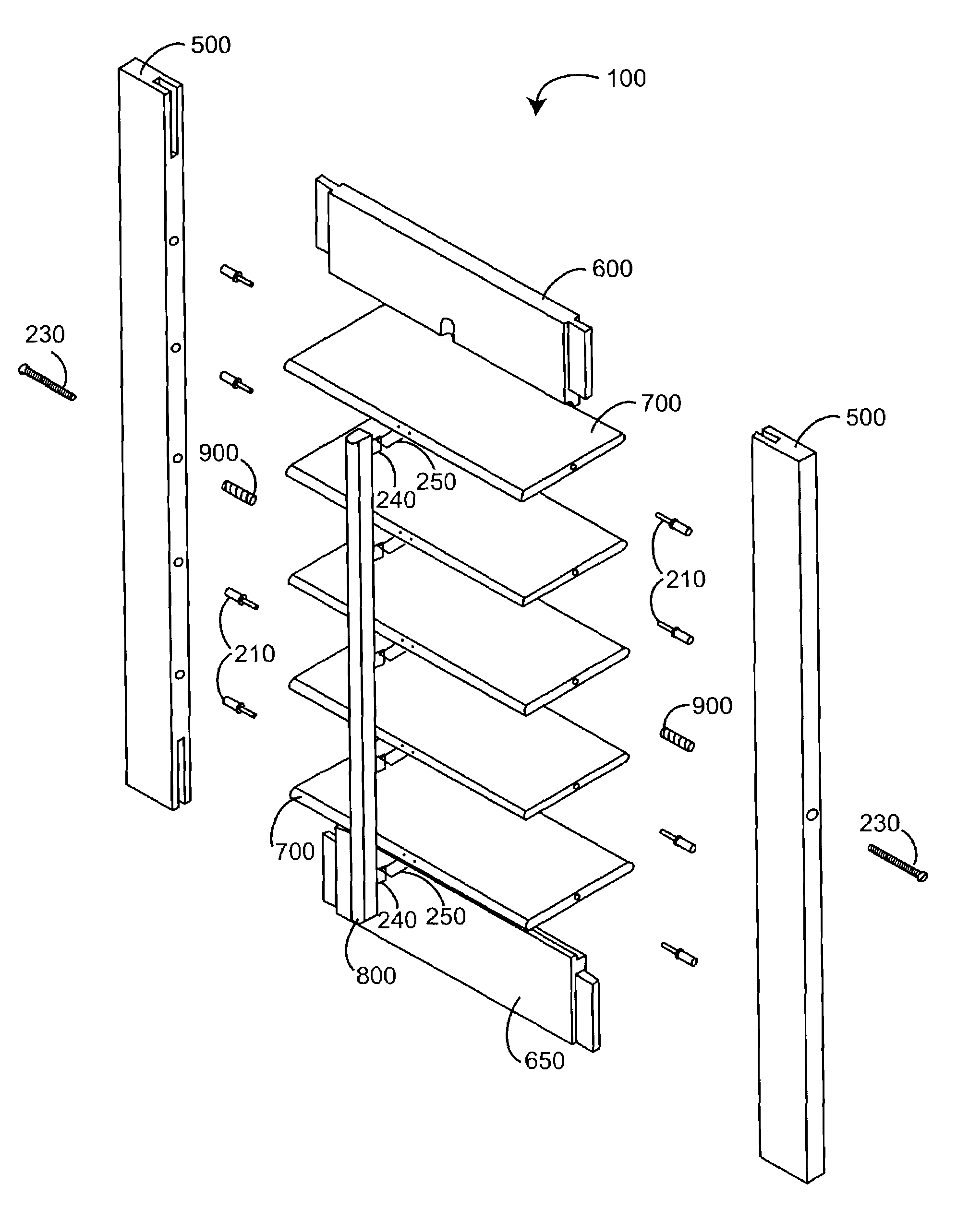
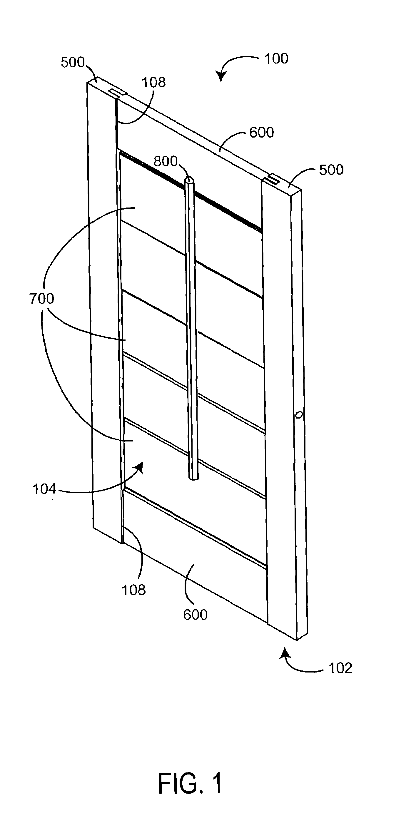
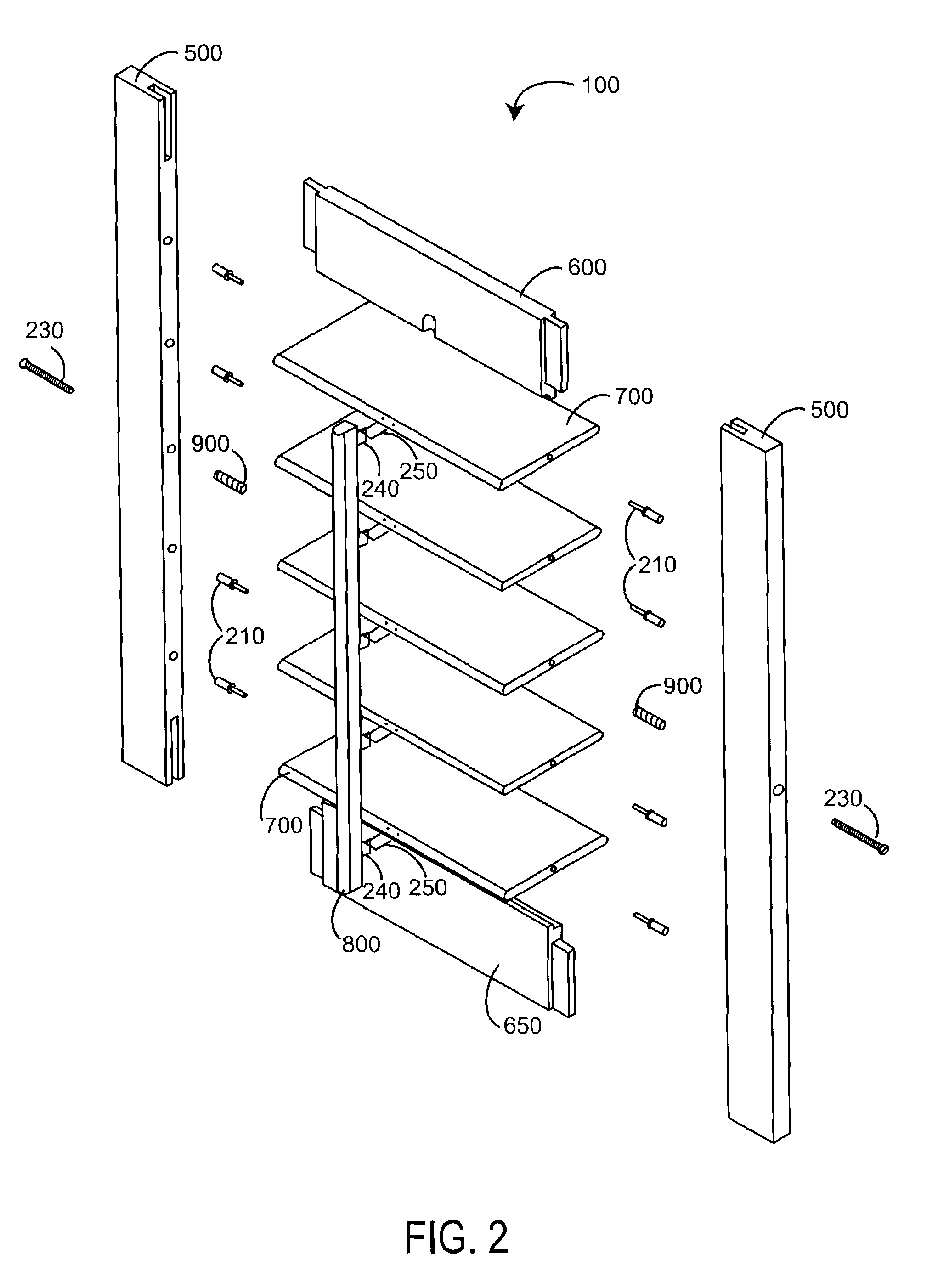
[0067]FIGS. 14A–G illustrate a full groove stile embodiment 1400, including a stile base 1500 (FIGS. 15A–C) and a groove insert 1600 (FIGS. 16A–C). An assembled full groove stile 1400 corresponds generally in configuration and function to the partial groove stile 500 (FIGS. 5A–D), described above. A pair of stiles 1400 provide mounts for louvers 700 (FIG. 1), having a number of pin holes 1610 spaced at regular intervals along the inside edge 1507 and configured to receive louver pins 210 (FIG. 2). Also, the stile 1400 has one or more tension adjustment holes 1550 configured to accept a tensioning screw 230 (FIG. 2) for louver tension control and frame stabilization, as described above.

[0068]As shown in FIGS. 14A–G, the full groove stile 1400 differs from the partial groove stile 500 (FIGS. 5A–D) in several respects. Advantageously, the full groove stile 1400 has two subcomponents, a stile base 1500 and a groove insert 1600. The stile base 1500 has an end-to-end groove 1510 instead o...

embodiment 150

[0075]FIG. 19 illustrates a rear-linked shutter embodiment 150 utilizing full groove stiles 1400 and capped louvers 1700. The rear-linked shutter 150 does not have a tilt bar 800 (FIG. 2), but instead has a link bar 1900. The link bar 1900 has multiple link bar holes 1910 adapted to attach to each of multiple louvers 1700 via snap-fit buttons 1880 (FIG. 18C). In one embodiment, the link bar 1900 is constructed of a thin planar, elongated, flexible material, such as plastic, and adapted to fit in the space between the louvers 1700 and stiles 1400. Advantageously, the view through the shutter 150 is not blocked by a tilt bar. Instead, the louvers 1700 are opened and closed by moving an individual louver 1700, which moves all louvers via the link bar 1900. Another advantage is that a tilt bar notch is eliminated in the top spreader, so that the spreaders 650 are the same part, reducing the number of parts and shutter manufacturing steps.


PUM

PropertyMeasurementUnit
Lengthaaaaaaaaaa
Widthaaaaaaaaaa

Abstract

A shutter manufacturing method provides a coated manufactured wood substrate sheet. A plurality of attached shutter components are identified. The attached shutter components are configured edge-to-edge and end-to-end so as to comprise the substrate sheet. The attached shutter components are separated into a plurality of prefinished shutter components, and the prefinished shutter components are incorporated into a shutter assembly.

Description

CROSS-REFERENCE TO RELATED APPLICATIONS[0001]This application is a continuation of prior U.S. patent application Ser. No. 09 / 954,541 filed Sep. 15, 2001, now U.S. Pat. No. 6,622,433, entitled Prefinished Medium Density Fiberboard Shutter, which relates to and claims the benefit of prior U.S. Provisional Application No. 60 / 233,307 entitled Pre-Coated Medium Density Fiberboard Shutter, filed Sep. 15, 2000, both prior applications incorporated by reference herein.BACKGROUND OF THE INVENTION[0002]Shutters are a high quality interior window treatment, having a combination of style, functionality and elegance that sets them apart from other window coverings. Shutters provide warmth in the winter and protect from damaging heat and sunlight in the summer. Shutters also provide complete control of view, privacy and light. Conventional shutters are made of an indigenous wood such as popular, oak or ash. The shutter components are typically assembled using doweling, screws and staples. After a...

Claims


Application Information

Patent Timeline
IPC IPC(8): B23P17/00E06B7/086
CPCE06B7/086Y10T29/4981Y10T29/39Y10T29/49789Y10T29/4984Y10T29/49996
Inventor BLACHLEY, DAVID
Owner BLACHLEY DAVID
Why Eureka
Try Eureka