Strategy for engine fueling during return to positive power flow after engine brake de-activation

a technology of positive power flow and engine, applied in the direction of machines/engines, output power, electric control, etc., can solve the problems of excess smoke, the rate at which the engine brake is released, and the transition may not be smooth as desired, so as to reduce the potential for misfire and the resulting generation of smoke in the exhaust.

Active Publication Date: 2006-06-06
INT ENGINE INTPROP CO LLC
View PDF8 Cites 3 Cited by
  • Summary
  • Abstract
  • Description
  • Claims
  • Application Information

AI Technical Summary

Benefits of technology

[0008]The present invention relates to a new and improved fueling strategy for fueling an engine during such a transition. The transitional strategy can provide smoother transitions from the beginning of engine brake de-activation until the resumption of positive power flow from the engine through the vehicle powertrain to the vehicle drivetrain. Consequently, the potential for misfire, and resulting generation of smoke in the exhaust, is significantly reduced.
[0010]The invention allows the use of a dump valve that can more rapidly dump the hydraulic control fluid from the engine brake actuator, while in doing so, providing control of engine fueling that is appropriate for such faster dumping of the control fluid.

Problems solved by technology

If fueling is not suitably controlled during the transition, the transition may not be as smooth as desired.
A rough transition is evidenced by engine misfire and the consequent generation of excess smoke in the engine exhaust.
It has been observed that a contributing factor to engine roughness during such transitions is the rate at which the engine brake releases.
If the hydraulic fluid that is activating the brake is not dumped sufficiently fast from the actuator, cylinder misfires and extra exhaust smoke may result.
For example, delayed release of a brake acting on engine exhaust valves can cause them to stay open longer than desirable, potentially causing misfires and extra smoke in the exhaust.

Method used


Image

  • Strategy for engine fueling during return to positive power flow after engine brake de-activation
  • Strategy for engine fueling during return to positive power flow after engine brake de-activation

Examples


Embodiment Construction

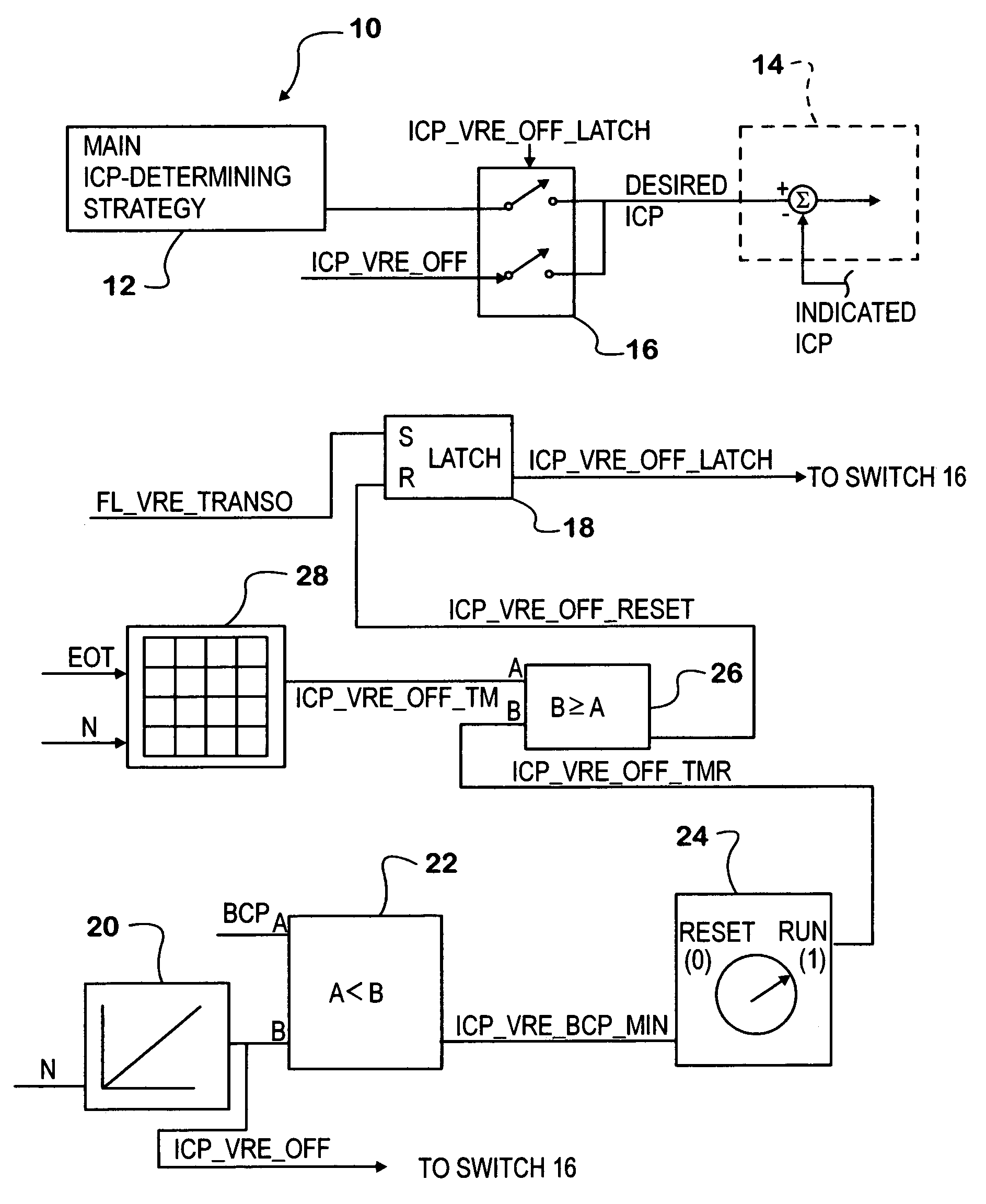
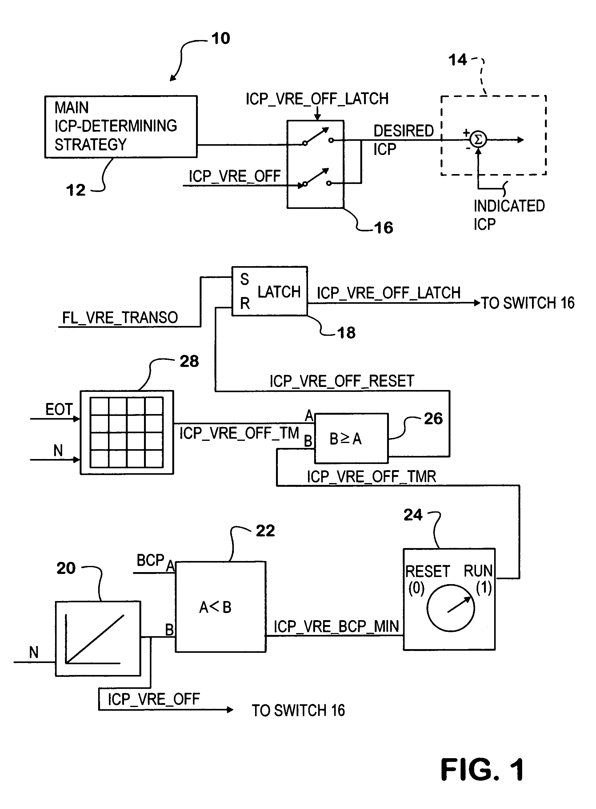
[0020]FIG. 1 shows a portion of a fuel control strategy embodied in an exemplary internal combustion engine control system 10. The particular engine is a diesel engine that has a fuel injection system controlled by the fuel control strategy and an engine brake that is activated by pressure of a hydraulic control fluid. Activation and de-activation of the engine brake are controlled by requests from a portion of control system 10 not specifically shown in FIG. 1. When the brake is being applied (activated), the control system causes hydraulic control fluid under pressure to be delivered to a hydraulic actuator. When the brake is to be released (de-activated), the control system causes the hydraulic control fluid to be dumped from the actuator, relieving the pressure in the actuator and allowing the brake to de-activate.

[0021]The engine comprises cylinders forming combustion chambers in which fuel injected by fuel injectors ignites in hot air that has entered through an intake system ...


PUM


Abstract

An internal combustion engine that propels a vehicle has a fuel injection system for injecting fuel into engine cylinders at desired injection control pressure. A control system controls activation and de-activation of a hydraulic actuator for an engine brake. A processor processes data to develop data for desired injection control pressure. Transitional injection control pressure data is used as desired injection control pressure during a transition time interval that commences with de-activation of the engine brake caused by the relief of pressure of the control fluid for allowing resumption of positive power flow from the engine for propelling the vehicle and that ends after the processor has determined the existence of a predetermined correlation between the transitional injection control pressure data and data indicating pressure of the control fluid.

Description

FIELD OF THE INVENTION[0001]This invention relates generally to internal combustion engines for propelling motor vehicles, and particularly to a transitional fueling strategy for fueling an engine as an engine brake that had previously been activated to slow the engine is being deactivated so that the engine can return to delivering positive power for propelling a vehicle.BACKGROUND OF THE INVENTION[0002]Various devices can be associated with an internal combustion engine that powers a motor vehicle to brake the engine by itself. Such engine brakes can be useful in larger vehicles like highway trucks. A known technique for retarding an internal combustion comprises augmenting engine back-pressure. One way of doing this comprises restricting the exhaust gas flow from the engine. In a conventional camshaft engine, a valve that is disposed in the exhaust system, sometimes called an exhaust brake, can be operated to restrict the exhaust gas flow. In an engine that has variable valve act...

Claims


Application Information

Patent Timeline
Patent Type & Authority Patents(United States)
IPC IPC(8): F02D1/00
CPCF02D9/06F02D13/04F02D41/021F02D2250/31F02D41/126F02D41/3836
Inventor MAJEWSKI, MICHAEL A.BEAUCAIRE, JAMES T.
Owner INT ENGINE INTPROP CO LLC
Why Eureka
Try Eureka