
Barometric pressure diesel timing controller

a timing controller and barometric pressure technology, applied in the direction of electric control, machines/engines, instruments, etc., can solve the problems of reducing fuel efficiency, increasing the temperature of the exhaust gas of the cylinder, reducing the firing pressure of the peak cylinder, and reducing the efficiency so as to reduce the untimely and incomplete combustion of the engine cylinder, the effect of optimizing engine efficiency

Inactive Publication Date: 2006-06-06
GENERAL ELECTRIC CO
View PDF19 Cites 18 Cited by
  • Summary
  • Abstract
  • Description
  • Claims
  • Application Information

AI Technical Summary

Benefits of technology

[0010]This engine intake air parameter could be the air pressure in the engine intake manifold or the turbocharger speed, for example. The intake air pressure type sensor can be in fluid communication with the engine intake manifold to sense the pressure therein. The turbocharger speed type sensor can be a tachometer output on the turbocharger, for example. In either case, the output of the engine intake air parameter sensor is connected to a barometric pressure timing controller. The barometric pressure timing controller compares the instantaneous engine intake air parameter with a nominal value of the engine intake air parameter and determines the instantaneous barometric pressure from that comparison. The barometric pressure timing controller then adjusts the fuel injection timing by controlling the fuel injection pump and the fuel injector according to changes in barometric pressure, to advance or retard fuel injection timing to reduce untimely and incomplete combustion in the engine cylinders. Engine efficiency may therefore be optimized, and exhaust emissions may be reduced, when the engine is operated at higher altitudes at a desired speed and power determined by a selected throttle position.
[0011]The barometric pressure timing controller is an electronic controller, such as a microprocessor with a memory of predetermined fuel injection timing values that have been found to minimize exhaust emissions while optimizing steady state engine operation under the corresponding barometric pressure, without exceeding a maximum peak firing pressure in the engine cylinders. Thus, the engine may be continuously and optimally operated under varying pressure conditions while minimizing exhaust emissions and maintaining optimum engine performance. As exhaust emissions are reduced, and combustion in the cylinders is more timely and complete, engine power deration due to turbocharger overspeed is largely avoided.

Problems solved by technology

When engines are operated at higher altitudes, i.e., at a low barometric pressure, lesser amounts of air are introduced into the cylinders, causing the air-fuel mixing process to be deteriorated relative to lower altitude, higher ambient pressure environments.
This combination of factors increases late and incomplete combustion in the engine cylinders, which lowers fuel efficiency and increases exhaust emissions of CO, PM, and smoke.
The reduced amount of air for the fuel-air mixture combustion, together with the increased amount of late and incomplete combustion, typically leads to reduced peak cylinder firing pressure and increased cylinder exhaust gas temperatures.

Method used


Image

  • Barometric pressure diesel timing controller
  • Barometric pressure diesel timing controller
  • Barometric pressure diesel timing controller

Examples


Embodiment Construction

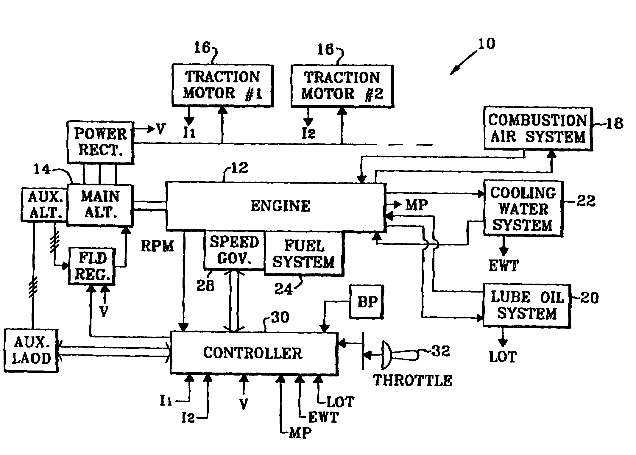
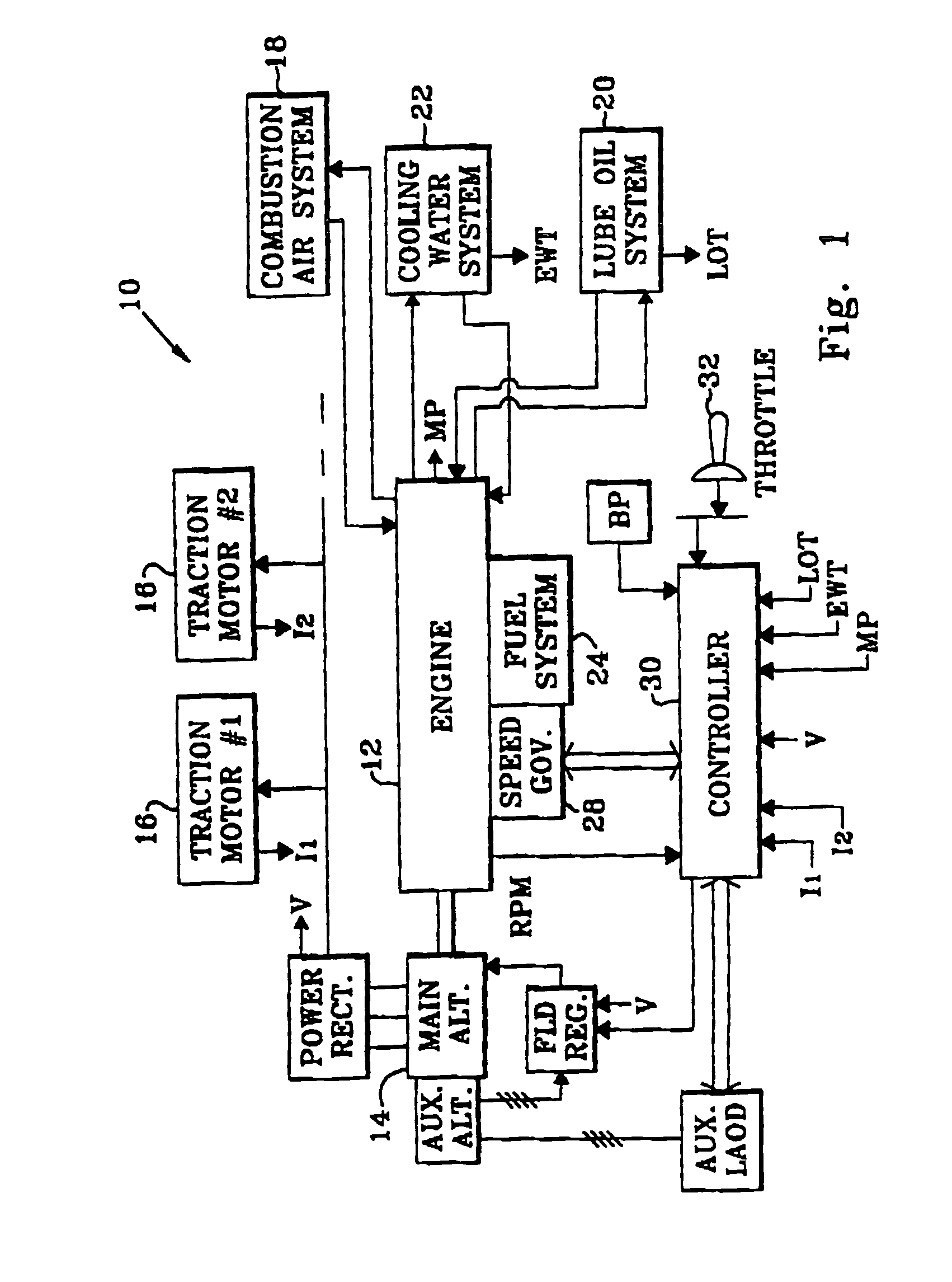
[0016]FIG. 1 is a schematic illustration of a propulsion system 10 including a diesel engine 12. Particularly, and in an exemplary embodiment, the system 10 is used in a self propelled locomotive. The engine 12 is mechanically coupled to a rotor of a main alternator 14 to power a plurality of traction motors 16 that are positioned on each side of an axle of the locomotive to propel the locomotive. While the present invention is described in the context of a locomotive, it is recognized that the benefits of the invention accrue to other applications of diesel engines, and to other varieties of diesel engines beyond that specifically described. Therefore, this embodiment of the invention is intended solely for illustrative purposes and is in no way intended to limit the scope of application of the invention.

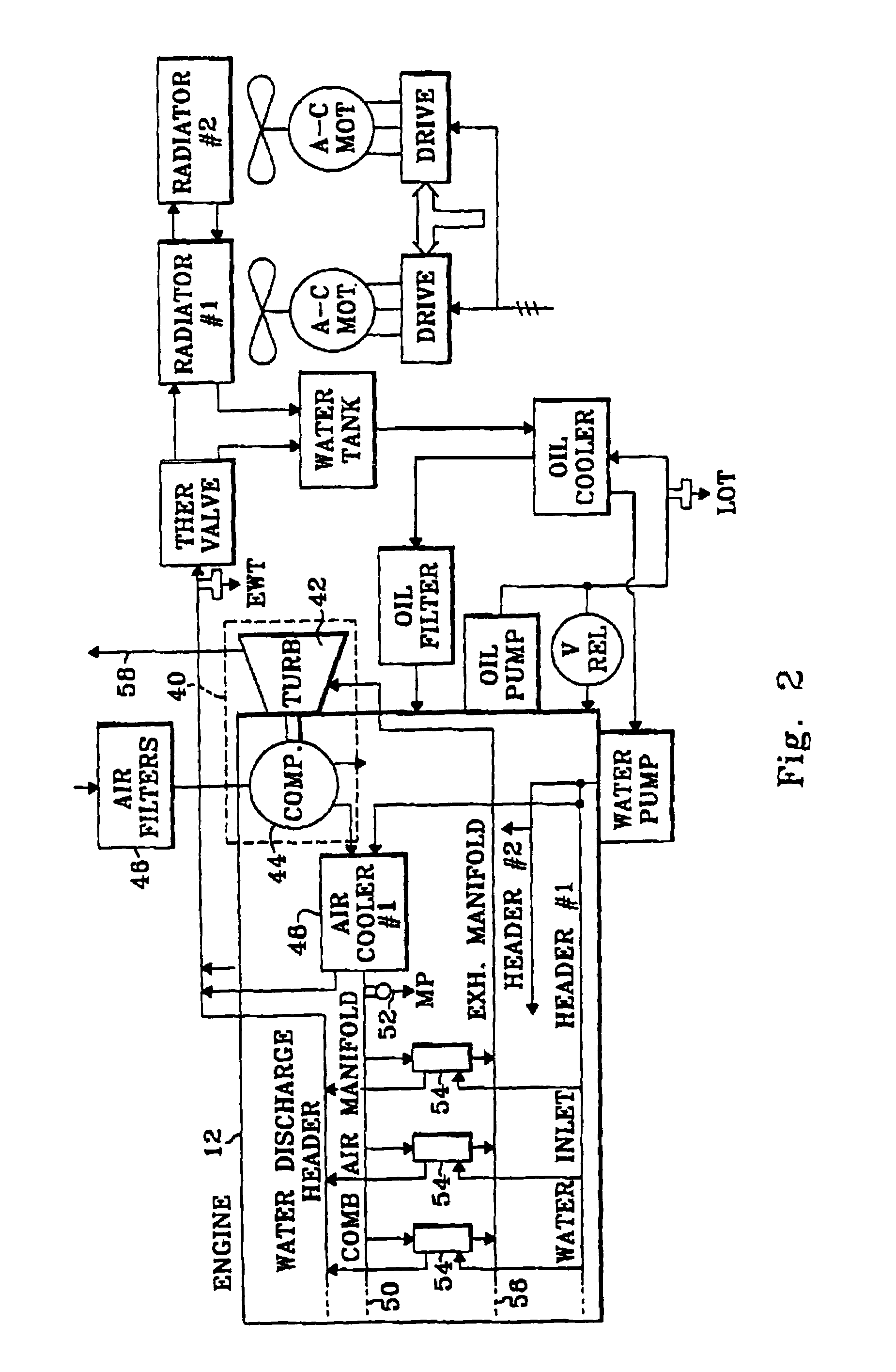
[0017]The engine 12 is a high horsepower, turbocharged, multiple-cylinder diesel engine, and includes a number of ancillary systems, such as a combustion air system 18, a lube oil ...


PUM


Abstract

A fuel injection timing control system for diesel engines operating at high altitude, including a sensor for a parameter of the engine intake air, such as engine intake air pressure or turbocharger speed. This sensor communicates with a barometric pressure timing controller, and a throttle position sensor communicates with the barometric pressure timing controller. Nominal values of the engine intake air parameter at various throttle notch settings and various engine performance parameters are stored in a table, for a nominal barometric pressure. The barometric pressure timing controller determines the instantaneous barometric pressure by adjusting the nominal barometric pressure based on the difference between the instantaneous value for the engine intake air parameter and the nominal value for the engine intake air parameter, at the known throttle notch setting and the known engine performance parameters. The barometric pressure timing controller then adjusts fuel injection timing in response to the thusly determined barometric pressure and the sensed throttle position, by advancing or retarding the fuel injection timing by predetermined values as the barometric pressure or the throttle position changes. The predetermined values of fuel injection timing are selected to reduce exhaust emissions and increase engine efficiency and performance under various barometric pressure conditions so that the engine may be operated continually and optimally under various barometric pressure conditions.

Description

CROSS REFERENCE TO RELATED APPLICATIONS[0001]This is a continuation patent application of U.S. patent application Ser. No. 11 / 031,571, filed on Jan. 6, 2005, now abandoned, and entitled “Barometric Pressure Diesel Timing Controller.”STATEMENT REGARDING FEDERALLY SPONSORED RESEARCH OR DEVELOPMENT[0002]Not ApplicableBACKGROUND OF THE INVENTION[0003]1. Field of the Invention[0004]This invention relates generally to diesel engines and, more particularly, to medium speed diesel engines for operation at high altitudes.[0005]2. Background Art[0006]Power is generated in a diesel engine by diffusing and combusting diesel fuel in a plurality of engine cylinders. Liquid fuel is injected into the engine cylinders, which are full of compressed air at high temperature. The fuel is broken up into droplets, which evaporate and mix with the air in the cylinders to form a flammable mixture. Complete and efficient combustion in the cylinders requires full oxidation of fuel through evaporation, species...

Claims


Application Information

Patent Timeline
Patent Type & Authority Patents(United States)
IPC IPC(8): F02M37/04
CPCF02D41/401F02B3/06F02B29/0412F02B29/0437Y02T10/44F02D41/0007F02D2200/0406F02B37/00Y02T10/40
Inventor GALLAGHER, SHAWN MICHAELDILLEN, ERIC RICHARD
Owner GENERAL ELECTRIC CO
Learn More