Both-side recording apparatus

a recording apparatus and a technology of side-by-side, applied in the direction of typewriters, thin material processing, article separation, etc., can solve the problems of increasing the size increasing the power of the driving source, and increasing the const, so as to reduce the size and cost of the recording apparatus, and reduce the load of the driving source. , the effect of enhancing the degree of freedom of control

Inactive Publication Date: 2006-06-06
CANON KK
View PDF8 Cites 11 Cited by
  • Summary
  • Abstract
  • Description
  • Claims
  • Application Information

AI Technical Summary

Benefits of technology

[0009]The present invention is to solve the technical problems as described above, and an object of the present invention is to provide a both-side recording apparatus, which is capable of enhancing the degree of freedom in control by bringing a reversing section roller into a state in which it is not started to operate as necessary, capable of reducing the apparatus size and cost by reducing a load of a driving source, and capable of enhancing conveying accuracy of a recording medium.

Problems solved by technology

However, there are several restrictions in the above described prior art examples.
Therefore, the driving source of the sheet feeding roller needs to rotate while excess load is exerted on the driving source, and therefore it is necessary to allow for the excess load and prepare the driving source capable of generating large torque, which causes the technical problems such as an increase in size, a rise in const, and further an increase in driving electric power.
Since the roller (reversing section roller) inside the sheet reversing section always rotates, the durability of the roller itself, such as the shaft, bearing and a rubber portion is required, and it is necessary to select the material having a favorable slidability, the material with allowance for deterioration and the like, which causes the problem of a rise in cost and the like.
Further, the driving gear train and the like to the reversing section roller always rotate, and therefore there arises the problem of increasing the noise occurring to the rotating portion.
In the type of the recording apparatus having the independent driving source inside the sheet reversing section, it becomes difficult to completely synchronize the circumferential speeds of the both rollers in the situation in which it is necessary to convey the recording sheet in cooperation of the sheet feeding roller and the reversing section roller, and there arises the problem that when a small dethroughtion between the circumferential speeds occurs, recording medium conveying accuracy is reduced due to occurrence of a slack of the sheet between both the rollers or an unnecessary tension.
As a result that the independent driving source is included, there arise the problems of an increase in the apparatus size, a rise in cost and the like.

Method used


Image

  • Both-side recording apparatus
  • Both-side recording apparatus
  • Both-side recording apparatus

Examples


second embodiment

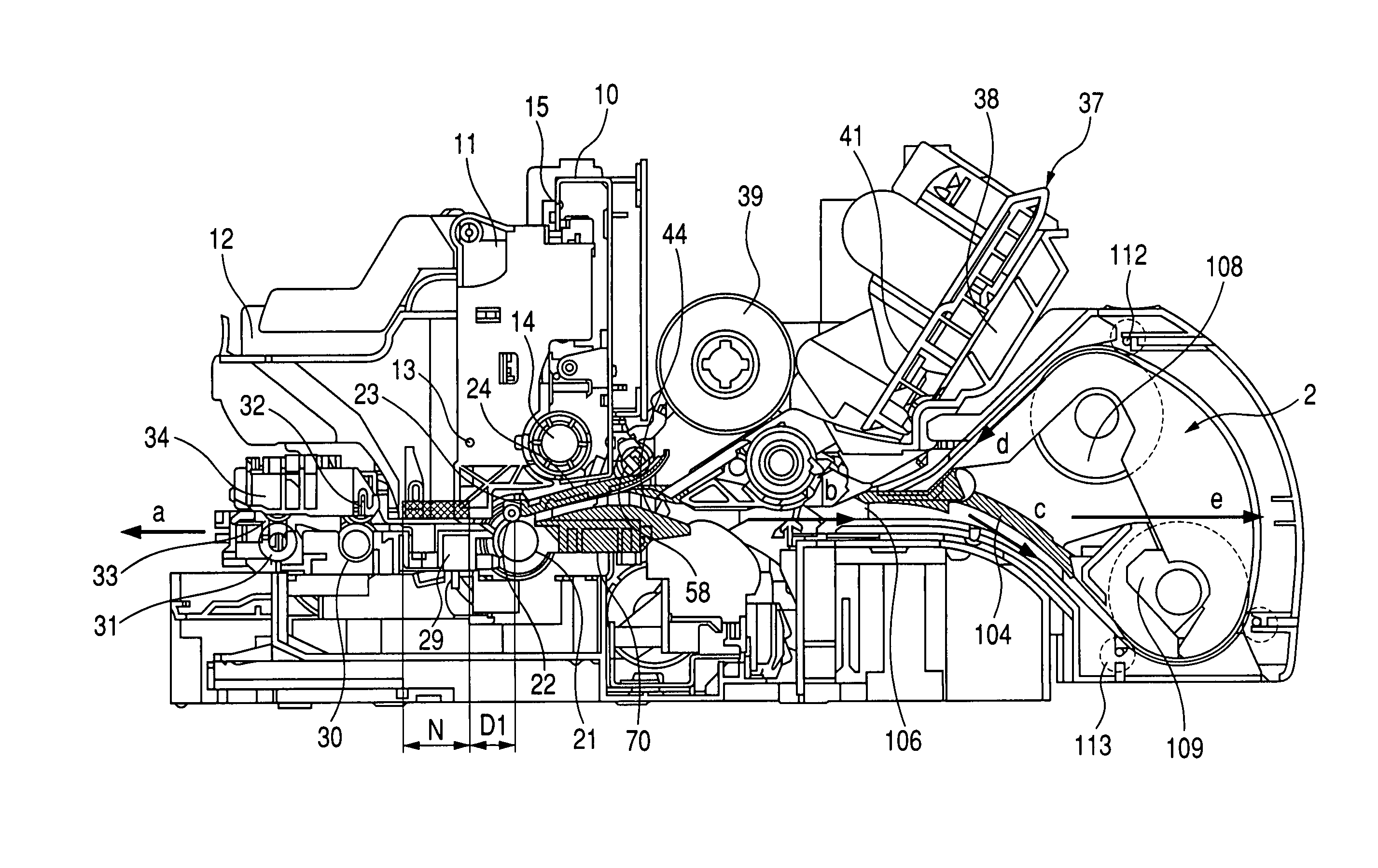
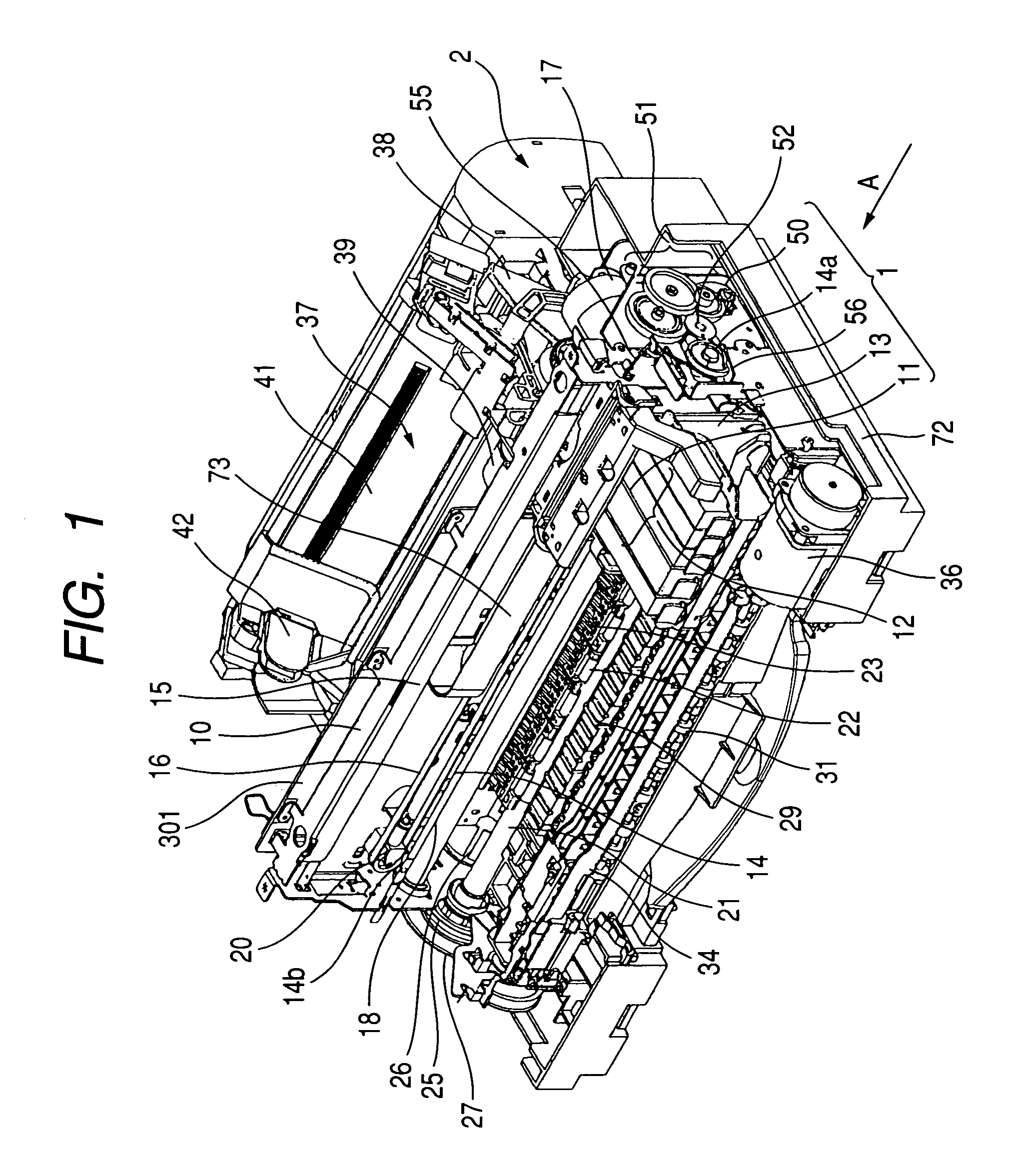
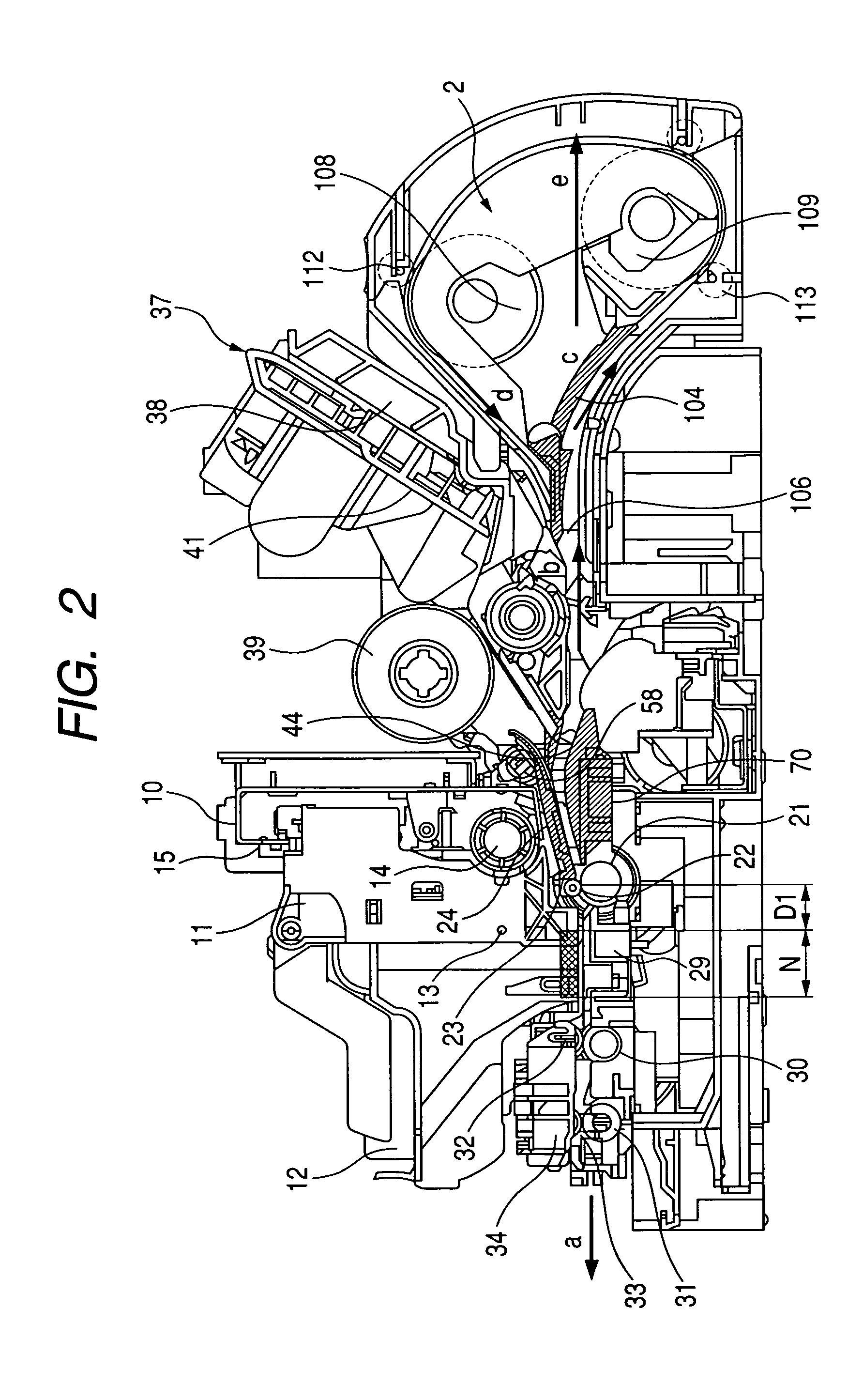
[0179]FIG. 23 is a schematic longitudinal sectional view showing a construction of an essential part of the both-side recording apparatus to which the present invention is applied. In the embodiment explained thus far, the mechanism including the spiral groove gear 120 and the stop arm 127 is used as the clutch mechanism (clutch means) which cuts off the driving force from the LF motor 26 to the both-side roller (reversing section roller) 108 or 109, but instead of this, the following construction can be adopted. In FIG. 23, reference numeral 133 denotes a lead screw provided with a spiral groove on a cylindrical surface, reference numeral 134 denotes a slider which slides to engage in the spiral groove of the lead screw 133 and slides synchronously with the rotation, reference numeral 135 denotes a slider arm portion which is an extension of a part of the slider 134, reference numeral 136 denotes an input gear fixed to the lead screw 133, reference numeral 137 denotes a clutch gear...

first embodiment

[0180]The clutch mechanism shown in FIG. 23 is used by connecting the both-side transmission gear train 115 shown in FIG. 15A to the input gear 136, and connecting the output gear 140 to the both-side roller idler gear 124 (FIG. 15A). This clutch mechanism is assembled so that the input gear 136 is rotated in the direction of the arrow a in FIG. 23 when the LF motor 26 rotates in the forward direction. With only the mechanism in FIG. 23, the power is not transmitted to the output gear 140 when the LF motor 26 rotates in the reverse direction from the arrow a in FIG. 23. Therefore, the rocker arm and the planetary gear not shown are provided at the last gear of the both-side transmission gear train 115 (FIG. 15A) in this embodiment, so that only when the LF motor 26 rotates in the reverse direction, the rocker arm not shown is engaged with the reverse rotation delay gear A121 (FIG. 15A). As a result, the operation in FIGS. 17A to 17C is performed as in the case of the The operation ...


PUM


Abstract

Driving sources of a reversing section roller and a sheet feeding roller are made common, a drive transmission mechanism to the reversing section roller is provided with clutch means for starting and stopping synchronous rotation after a predetermined rotation, and a degree of freedom in control is enhanced by properly bringing the reversing section roller into a halted state as necessary, thereby realizing reduction in load on the driving source, reduction in noises, and reduction in the size of the apparatus and cost. The apparatus is provided with clutch means, which starts synchronous rotation of the reversing section roller with the sheet feeding roller is started in a period of time from a start of a drive of the sheet feeding roller until nipping of a recording medium by the reversing section roller, after recording is performed onto a front surface, and stops the synchronous rotation of the reversing section roller with the sheet feeding roller in a period of time from release from the reversing section roller until finishing of a sheet discharge operation, after the recording medium from a sheet reversing section is nipped by the sheet feeding roller again.

Description

[0001]This application claims priority from Japanese Patent Application No. 2003-196519 filed Jul. 14, 2003, which is hereby incorporated by reference.BACKGROUND OF THE INVENTION[0002]1. Field of the Invention[0003]The present invention relates to a both-side recording apparatus including a sheet reversing section for automatically recording onto both of front and reverse surfaces of a recording medium.[0004]2. Related Background Art[0005]Various methods have been conventionally carried out or proposed as constructions for performing automatic both-side recording in recording apparatuses such as an ink jet recording apparatus and the like. In each of them, after recording onto a front surface (front side) of a recording sheet as a recording medium is finished, the conveying direction up to this time is reversed to feed (convey) the recording sheet into a sheet reversing section (a front and back reversing device), then, after the reversing operation is finished, the recording sheet ...

Claims


Application Information

Patent Timeline
Patent Type & Authority Patents(United States)
IPC IPC(8): B65H9/00B41J11/00B41J3/60B41J11/42B65H85/00
CPCB41J3/60
Inventor OHASHI, TETSUYO
Owner CANON KK
Why Eureka
Try Eureka