
Through hub oil fill and vent for a fluid dynamic bearing motor

a fluid dynamic bearing and filling technology, applied in the field of spindle motors, can solve the problems of poor resistance to mechanical shock and vibration, damage to the disc drive, data loss, etc., and achieve the effects of reducing the leakage and evaporation of oil, and extending the life of the motor

Inactive Publication Date: 2006-06-06
SEAGATE TECH LLC
View PDF4 Cites 22 Cited by
  • Summary
  • Abstract
  • Description
  • Claims
  • Application Information

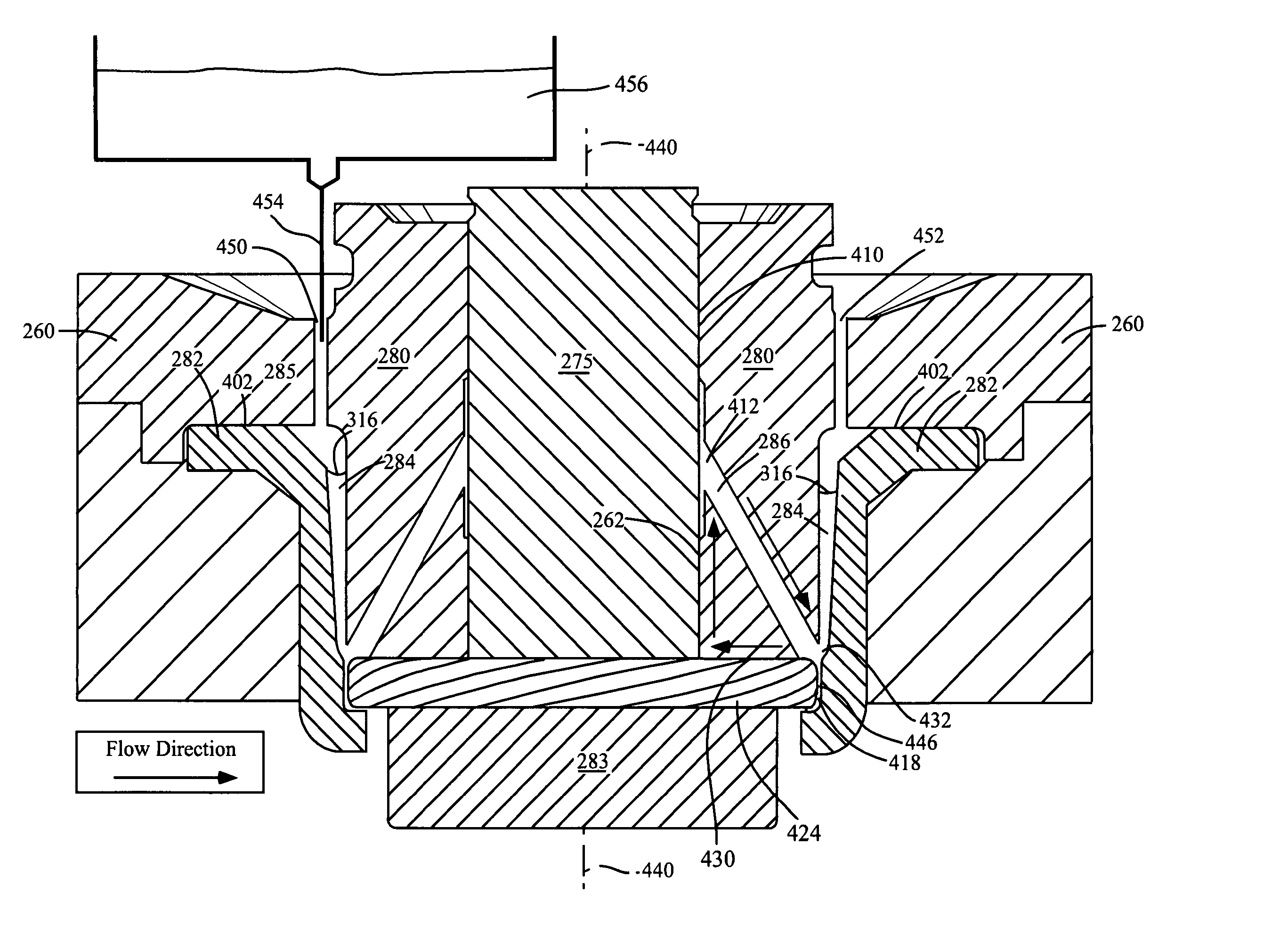
AI Technical Summary

Benefits of technology

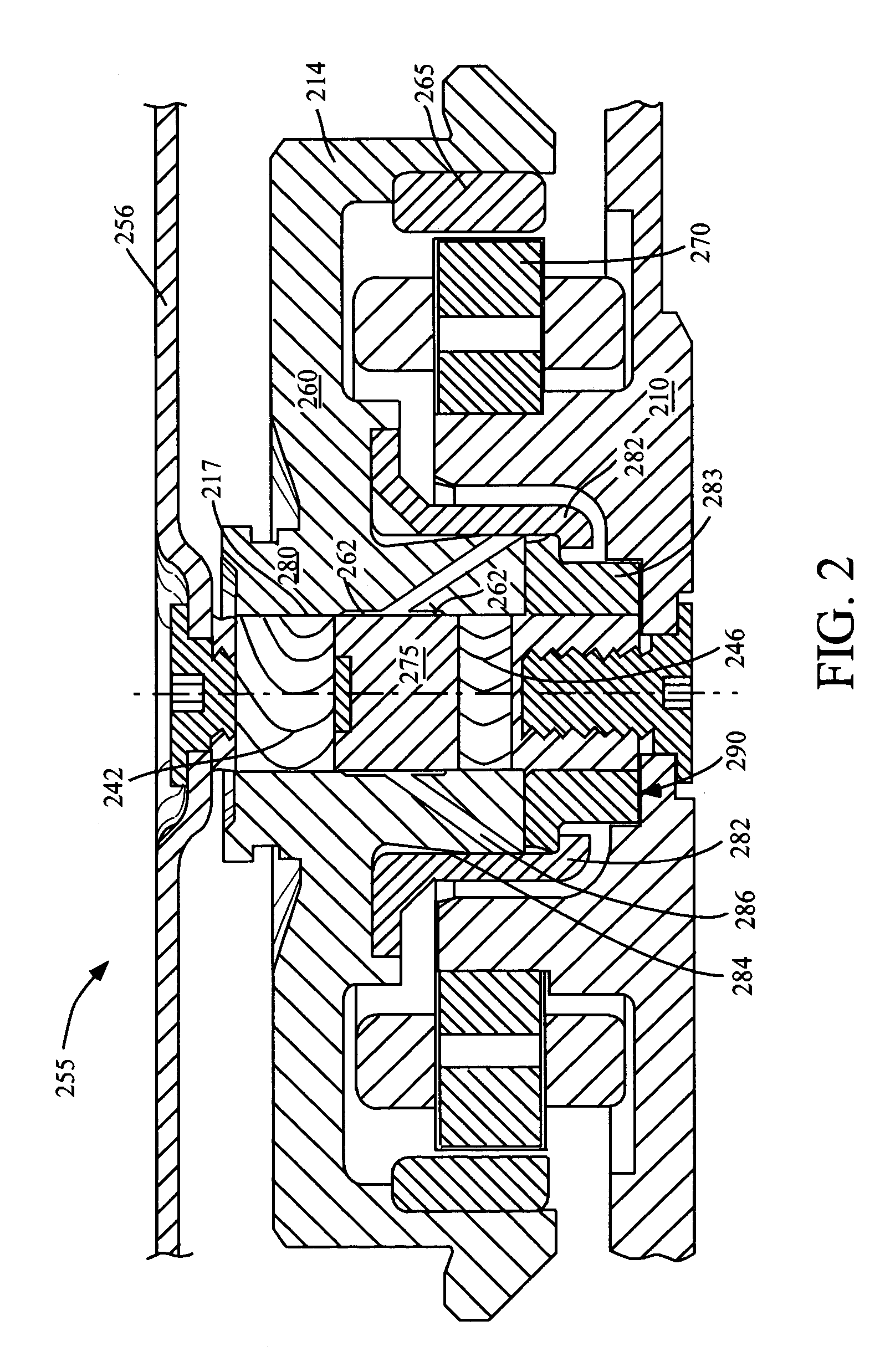
[0009]A through hub oil fill and air vent is provided for spindle motors. Oil leakage and evaporation from a motor is reduced, potentially extending motor life. In an embodiment, the present invention provides for oil retention under conditions of a shock event of at least 1000 G. The present invention may be used with top cover attach motors, additionally providing a more robust motor.
[0010]The process of filling oil into a spindle motor is made easier from a motor set up and tooling perspective. In conventional designs, the hub typically is removed or oil fill is performed prior to installation of the hub. Additionally, in an embodiment, bottom shield motor designs can be filled in a normal orientation, rather than filled at an angle or filled in an inverted orientation. Further, the through hub oil fill design allows for use with a relatively large diameter oil jet fill dispenser head, and further allows for subambient fill methods, ambient fill methods, injection fill methods or micro dispenser fill methods. A measured and controlled amount of oil or hydrofluid can therefore be dispensed into the motor, reducing any variability in the motor filling process.
[0011]Features of the invention are achieved in part by forming an oil fill and air vent passageway through a hub. As compared to previous designs, a longer oil diffusion path from within the motor is provided. In previous designs, oil is filled through a shield having a fill hole that extends a shorter length than a hub fill hole. The present invention eliminates the shield as a potential oil leakage source by utilizing a shield without a fill or vent hole.
[0012]Moreover, as compared to conventional designs, the present invention positions the oil fill passageway a greater distance from the motor oil reservoir, further reducing oil loss. In an embodiment, the hub oil channel and vent hole have a varying diameter and geometry, and can be angled, utilizing centrifugal forces, further reducing oil leakage. In an embodiment, an additional cavity is employed within the hub, substantially opposite the hub oil fill channel, for maintaining rotor rotational balance.

Problems solved by technology

A slight wobble or run-out in disc rotation can cause the disc to strike the read / write head, possibly damaging the disc drive and resulting in loss of data.
Imperfections in the raceways and ball bearing spheres result in vibrations.
Also, resistance to mechanical shock and vibration is poor in the case of ball bearings, because of low damping.
Vibrations and mechanical shock can result in misalignment between data tracks and the read / write transducer.
These shortcomings limit the data track density and overall performance of the disc drive system.
Because this rotational accuracy cannot be achieved using ball bearings, disc drives currently utilize a spindle motor having fluid dynamic bearings between a shaft and sleeve to support a hub and the disc for rotation.
Further, hydrodynamic bearings can be scaled to smaller sizes whereas ball bearings have smallness limitations.
However, hydrodynamic bearings suffer from sensitivity to external loads or mechanical shock events.
Fluid can in some cases be jarred out of the bearing by vibration or shock events.
Further, bearing fluid is susceptible to evaporation over time.
These particles can deposit on the read / write heads and the surfaces of the discs, causing damage to the discs and the read / write heads as they pass over the discs.
However, tests show that recent radial capillary seal designs fail at about 500 Gs of shock, and fluid leaks through fill holes at about 500 Gs of shock.
Laptop or portable computers can be subjected to large magnitudes of mechanical shock as a result of handling.
If excessive fluid is loaded into the bearing, the fluid will escape into the surrounding atmosphere landing on the surface of the disc and degrade the performance of the disc drive.
If insufficient fluid is loaded into the bearing, then the physical bearing surfaces could contact, leading to increased wear and eventual failure of the bearing system.
Further, current oil fill and air evacuation methods for fluid dynamic bearings are relatively complex and costly due to the often awkward filling angles and tight clearances.
It can be difficult to consistently accurately load fluid into the sharp corners of a shield hole.
Further, current oil filling methods can leave a considerable amount of excess oil on the surfaces of the sleeve, which must be subsequently removed through an arduous post-cleaning process.
The cleaning process can amount to ten percent of the total assembly cost of the motor.

Method used


Image

  • Through hub oil fill and vent for a fluid dynamic bearing motor
  • Through hub oil fill and vent for a fluid dynamic bearing motor
  • Through hub oil fill and vent for a fluid dynamic bearing motor

Examples


Embodiment Construction

[0021]Exemplary embodiments are described with reference to specific configurations. Those of ordinary skill in the art will appreciate that various changes and modifications can be made while remaining within the scope of the appended claims. Additionally, well-known elements, devices, components, methods, process steps and the like may not be set forth in detail in order to avoid obscuring the invention.

[0022]An apparatus and method is described herein for filling and venting a fluid dynamic bearing motor and other spindle motors. By employing a hub having a fill hole and vent hole, oil leakage and oil evaporation is reduced, and the oil filling process is simplified. The present invention is especially useful with motor designs where a shield is employed adjacent to a sleeve having a fluid reservoir therebetween.

[0023]It will be apparent that features of the discussion and claims may be utilized with disc drives, low profile disc drive memory systems (including one-inch disc driv...


PUM

PropertyMeasurementUnit
angleaaaaaaaaaa
velocityaaaaaaaaaa
diameteraaaaaaaaaa

Abstract

A through hub fill hole and air vent having an enlarged fluid diffusion path is provided for spindle motors. Oil leakage and evaporation from a motor is reduced. In an aspect, oil is retained under conditions of at least a 1000 G shock event. In an aspect, the hub fill hole has a varying diameter and geometry, and is angled, further reducing oil leakage. In an aspect, an additional cavity is employed within the hub, for maintaining rotor rotational balance. The process of filling oil into a spindle motor is made easier from a motor set up and tooling perspective. Removal of the hub and other motor components is not necessary for filling a motor. Large diameter oil fill dispenser heads, subambient and ambient fill processes, and micro dispenser fill processes may be utilized. A measured and controlled amount of oil can be dispensed, reducing variability in the motor filling process.

Description

CROSS REFERENCE TO RELATED APPLICATION[0001]This application is based on a provisional application No. 60 / 483,029, filed Jun. 27, 2003, entitled Through Hub Oil Fill And Vent For Fluid Dynamic Motors, and assigned to the Assignee of this application and incorporated herein by reference.FIELD OF THE INVENTION[0002]The invention relates generally to spindle motors, and more particularly to filling and venting a fluid dynamic bearing for use with disc drive data storage systems.BACKGROUND OF THE INVENTION[0003]The recent new environments for usage of disc drive memory systems have intensified design and performance needs including needs for heightened robustness. Besides traditional computing environments, disc drive memory systems are used more recently by devices including digital cameras, digital video recorders, laser printers, photo copiers, jukeboxes, video games and personal music players. Disc drive memory systems store digital information that is recorded on concentric tracks ...

Claims


Application Information

Patent Timeline
Patent Type & Authority Patents(United States)
IPC IPC(8): F16C32/06F16C17/10F16C33/10F16C33/74G11B19/20
CPCF16C17/026F16C17/10F16C33/107G11B19/2009G11B19/2027F16C33/74F16C2370/12
Inventor WEINGORD, JERRYLEE, JAMES SIDNEY
Owner SEAGATE TECH LLC
Learn More