Modular propeller

a module and propeller technology, applied in the direction of waterborne vessels, machines/engines, rigid support of bearing units, etc., can solve the problems of affecting the performance of engines, so as to improve engine performance and reduce production costs

Active Publication Date: 2006-06-06
STAHL BRADFORD C
View PDF11 Cites 55 Cited by
  • Summary
  • Abstract
  • Description
  • Claims
  • Application Information

AI Technical Summary

Benefits of technology

[0009]Another advantage of the present invention is that a modular propeller assembly is provided that is inexpensive to manufacture.
[0010]A further advantage of the present invention is that a modular propeller assembly is provided that is stronger than prior art units.
[0011]Another advantage of the present invention is that a modular propeller assembly is provided that has exhaust chambers that are divided by vanes which improve engine performance.
[0012]A still further advantage of the present invention is that a modular propeller assembly is provided with counter rotating assemblies, and has twice the benefit.

Problems solved by technology

Replacing a broken blade in the field becomes much more difficult if it is jammed too tightly in the hub.
The high taper angles also cause the blade to become loose while flexing under load in the completed assembly.

Method used


Image

  • Modular propeller
  • Modular propeller
  • Modular propeller

Examples


Embodiment Construction

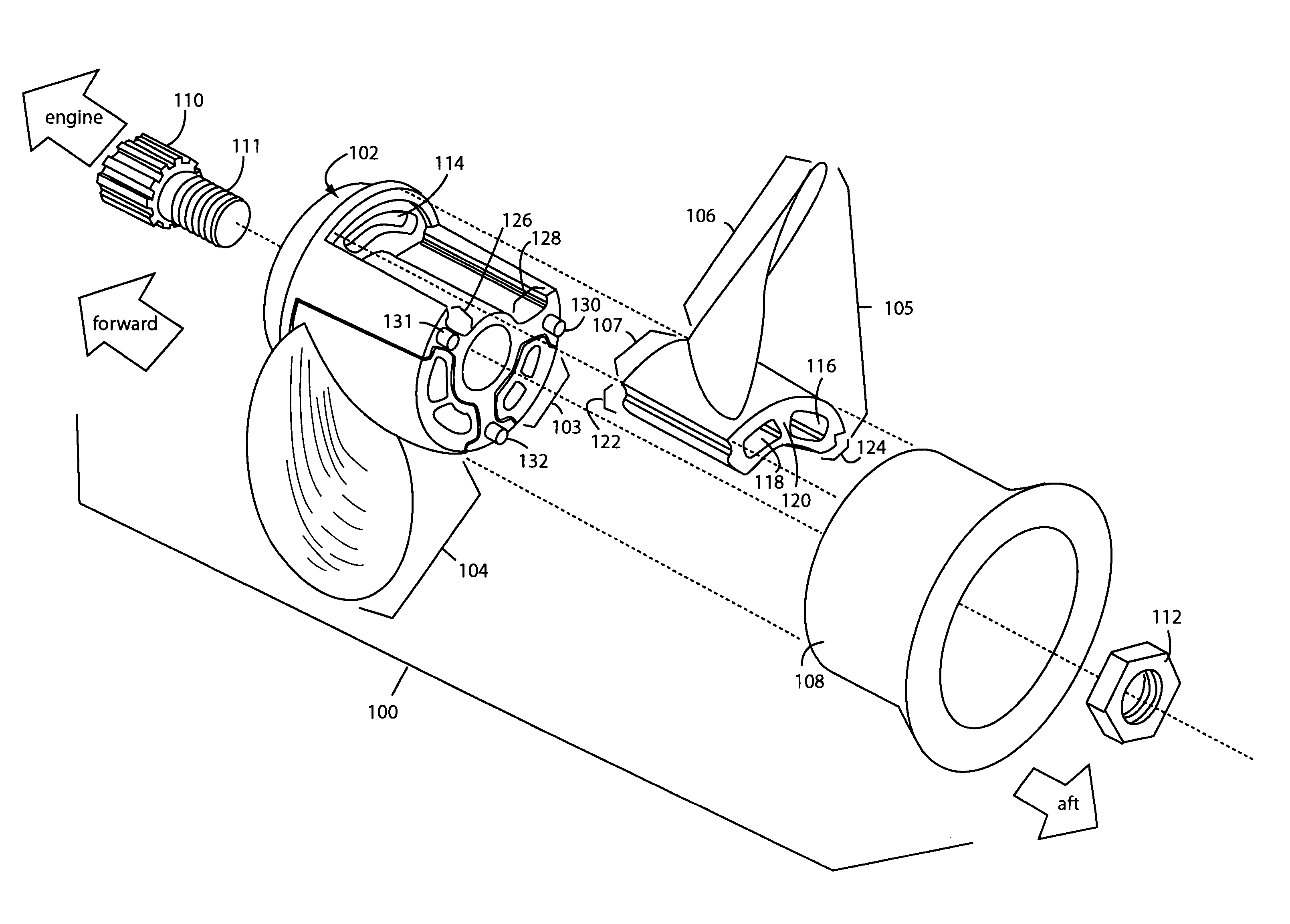
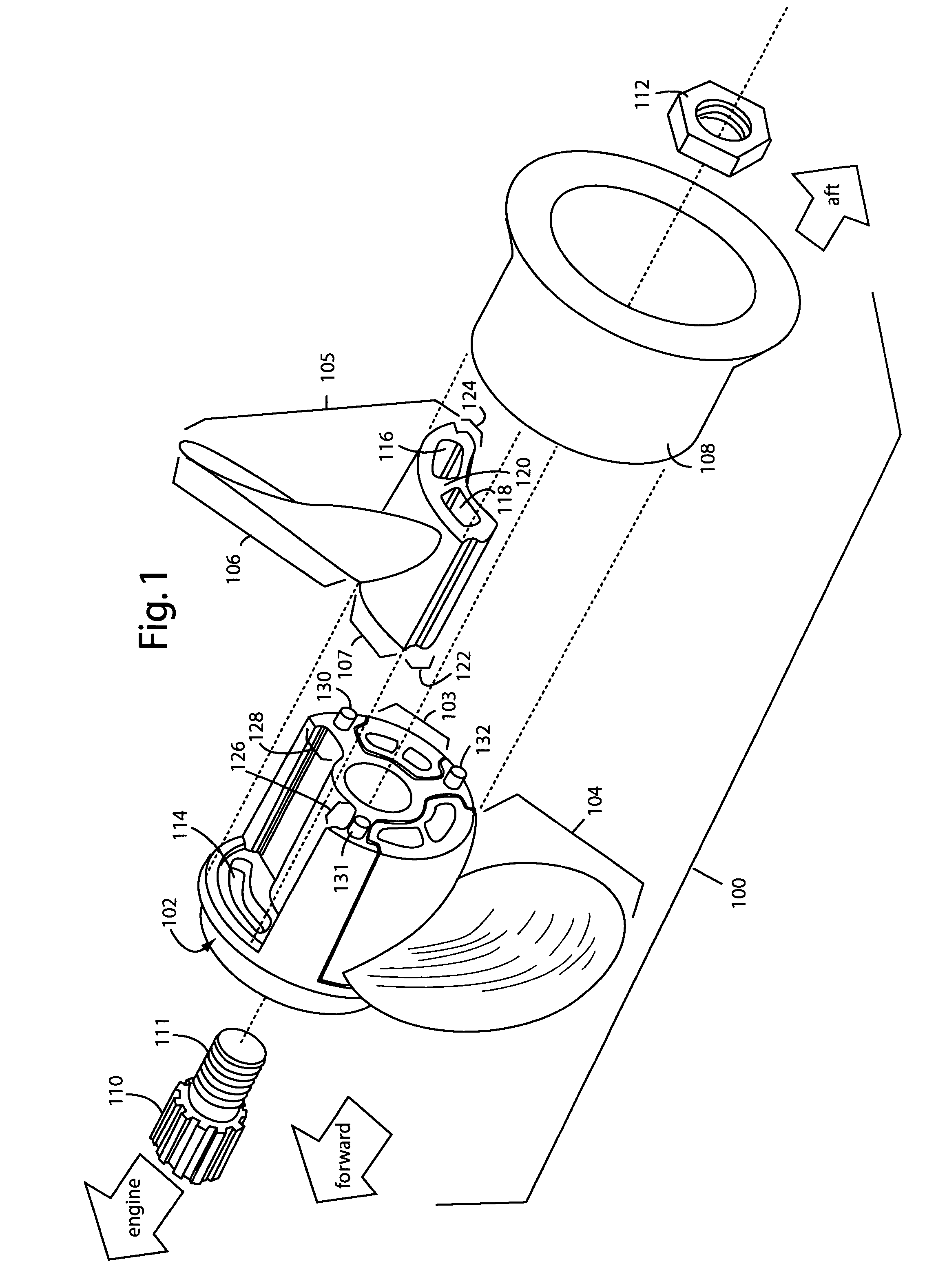
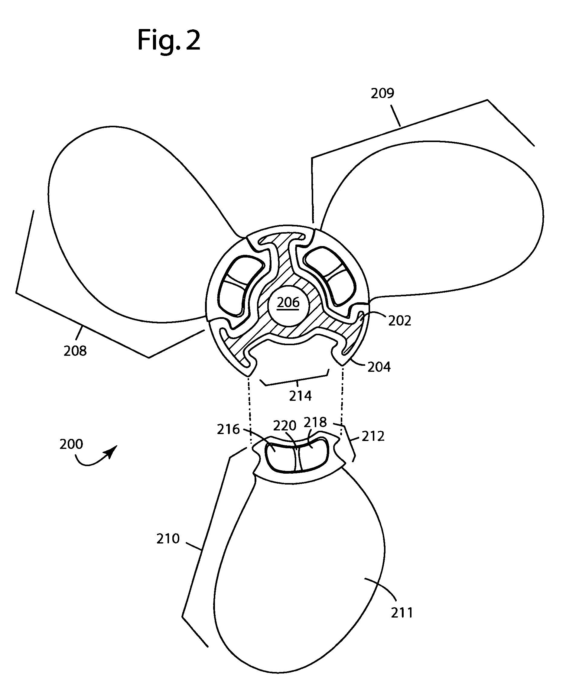
[0020]FIG. 1 illustrates a modular propeller embodiment of the present invention, referred to herein by the reference numeral 100. The propeller 100, in this example, is useful on inboard / outboard and outboard boat motors and comprises a center hub 102, an interlocking replaceable propeller blade units 103–105. Each replaceable propeller blade unit, e.g., 105, includes a blade 106 and a root 107. A rear cap 108 secures the replaceable propeller blade units 103–105 to the center hub 102. The assembled modular propeller 100 typically mounts on a splined shaft 110 of an outboard marine engine. A threaded portion 111 is used to fasten the whole assembly with a machine nut 112. The replaceable propeller blade units 103–105 are all identical, and commercial implementations allow users to choose a variety of sizes and blade pitches. As few as two and as many as six evenly distributed blades can be used in various embodiments of the present invention. Typical applications are 8–18 inch diam...


PUM


Abstract

A modular propeller comprises a center hub with an integrated front cap and an aluminum core encapsulated with fiber-reinforced composite polymer resin. A set of replaceable blades have bases that slip into and interlock with corresponding slots in the center hub. An elongated rear cap retains the blades in the center hub. The rear cap includes a nozzle section for expelling exhaust gasses that pass through the center parts of the hub and blade bases.

Description

BACKGROUND OF THE INVENTION[0001]1. Field of the Invention[0002]The present invention relates to propellers, and more particularly to modular propellers used on boats that allow the individual blades to be replaced.[0003]2. Description of Related Art[0004]A plastic marine propeller and hub assembly is described by the present inventor, Brad Stahl, in U.S. Pat. No. 4,930,987, issued Jun. 5, 1990, herein “Stahl '987”. Three plug-in blade roots are slipped into an interlocking hub between front and rear end caps. All the parts are made of injection-molded high-strength fiber-reinforced plastic. The manufacturing costs of such propellers are said to be half the cost of conventional metal propellers. Typical applications are 16–18 inch diameter three blade propellers intended for 90–250 horsepower motors.[0005]A double propeller is described in U.S. Pat. No. 5,423,701, issued Jun. 13, 1995, to Christian Rodskier, et al. The inner sleeves of the respective propeller hubs includes axial pa...

Claims


Application Information

Patent Timeline
Patent Type & Authority Patents(United States)
IPC IPC(8): B63H1/20B63H1/00B63H1/14B63H1/26B63H5/10
CPCB63H1/14B63H5/10B63H1/26B63H1/20
Inventor STAHL, BRADFORD C.
Owner STAHL BRADFORD C
Why Eureka
Try Eureka