Color/mono switched display

a technology of switching display and monochrome, applied in the field of color/mono switching display, to achieve the effect of simple and efficient manner

Active Publication Date: 2006-06-06
KOPIN CORPORATION
View PDF13 Cites 21 Cited by
  • Summary
  • Abstract
  • Description
  • Claims
  • Application Information

AI Technical Summary

Benefits of technology

[0007]Therefore, a need exists for a method and apparatus to circumvent this “color breakup” phenomenon in a simple and efficient manner.

Problems solved by technology

One complication is the fact that monochrome displays typically operate at a slower frame rate (50–60 Hz) than color sequential displays (180–240 Hz), and that LC devices are typically optimized for a particular frame rate.

Method used


Image

  • Color/mono switched display
  • Color/mono switched display
  • Color/mono switched display

Examples


Embodiment Construction

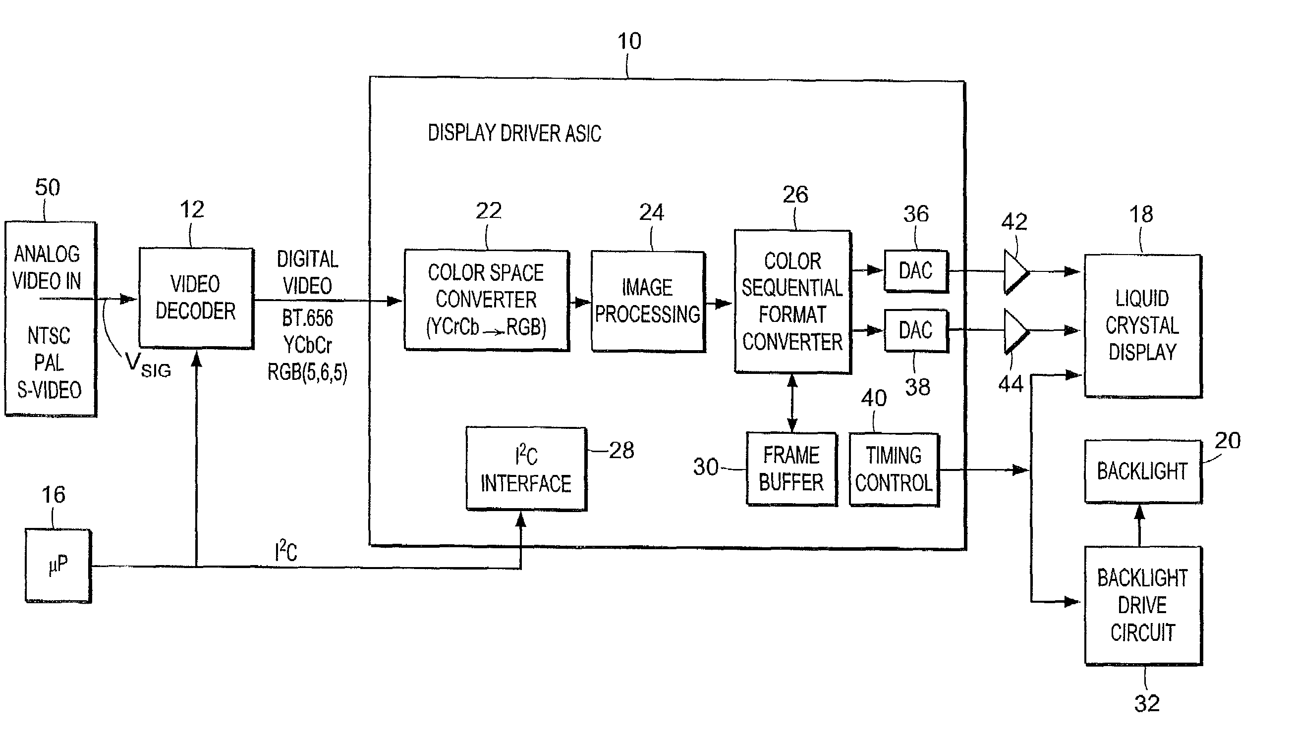
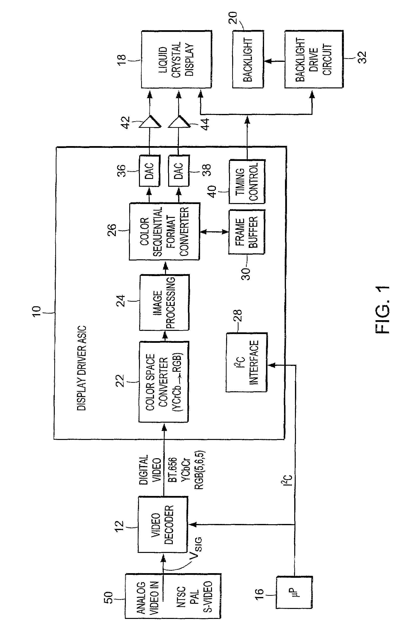
[0018]A first embodiment of a display system will now be described in connection with the block diagram of FIG. 1. Analog video signals in composite (NTSC / PAL) or S-Video formats from a video source 50 such as a video camera or video broadcast station are coupled to a video decoder 12. The decoder converts the analog signals to digital signals under the control of microprocessor 16 and extracts various components of the standard composite video signal Vsig and outputs digital video in any of several formats, including BT.656 with embedded sync, YCrCb with separate sync, or Red Green Blue (RGB) color signals. Note: The video decoder 12 is not needed if a digital video signal is available.

[0019]A display driver ASIC 10 accepts digital video input in standard format and outputs analog video to display 18 in color sequential format and generates timing and control signals for display 18 and external backlight drive circuit 32. A color space converter 22 converts video data to or from th...


PUM


Abstract

A color sequential display operative in one of two alternate modes. The first mode is a color sequential mode in which primary color images are displayed in successive frames while respective background light sources are simultaneously flashed on the display. The second mode is a monochrome mode in which the luminance Y signal is displayed in successive frames along with flashes of background white light.

Description

BACKGROUND OF THE INVENTION[0001]Flat-panel displays (FPD's) have been developed which utilize liquid crystals (LC) or electroluminescent materials to produce high quality images. These displays are expected to continue to supplant cathode ray tube (CRT) technology in more applications, due to FPDs relatively smaller size and weight. A promising route to large scale high quality liquid crystal displays (LCDs) is the active-matrix approach in which thin-film transistors (TFTs) are co-located with LCD pixels. An advantage of the active matrix approach using TFTs is the elimination of cross-talk between pixels, and the excellent grey scale that can be attained with TFT-compatible LCDs.[0002]One method (spatial color) of producing colored images for flat panel displays is to use an array of primary colored pixels. In a common approach, a pattern of red, green, and blue filters is applied to a surface of an LCD. The display is illuminated with white light, but each pixel controls light o...

Claims


Application Information

Patent Timeline
Patent Type & Authority Patents(United States)
IPC IPC(8): H04N9/12H04N9/30H04N9/31
CPCG09G3/3406H04N9/3114H04N9/3108G09G2300/0426G09G2310/0235G09G2360/18G09G2340/06
Inventor HERRMANN, FREDERICK P.
Owner KOPIN CORPORATION
Why Eureka
Try Eureka