Heat dissipation structure

Active Publication Date: 2006-06-06
DENSO CORP
View PDF9 Cites 11 Cited by
  • Summary
  • Abstract
  • Description
  • Claims
  • Application Information

AI Technical Summary

Benefits of technology

[0010]When the contact surface has the free energy E equal to or higher than 20 mN/m, preferably 34 mN/m, the grease is more likely to adhere to the contact surface and therefore the grease does not flow. When the contact surface has the roughness equal to or higher than 1.0 μm, preferably 2.5 μm, the surface roughness prod

Problems solved by technology

However, mounting such a heat sink is a costly process and therefore a heat dissipation structure having the heat sink cannot be reduced in cost.
Furthermore, the heat sink cannot be used for dissipating heat produced by the surface mount device.
Moreover, thermal stress is not applied to the electronic component because the grease is not cured.
However, it is difficult to retain the grease in a predetermined position due to its flo

Method used


Image

  • Heat dissipation structure
  • Heat dissipation structure
  • Heat dissipation structure

Examples


Example

First Embodiment

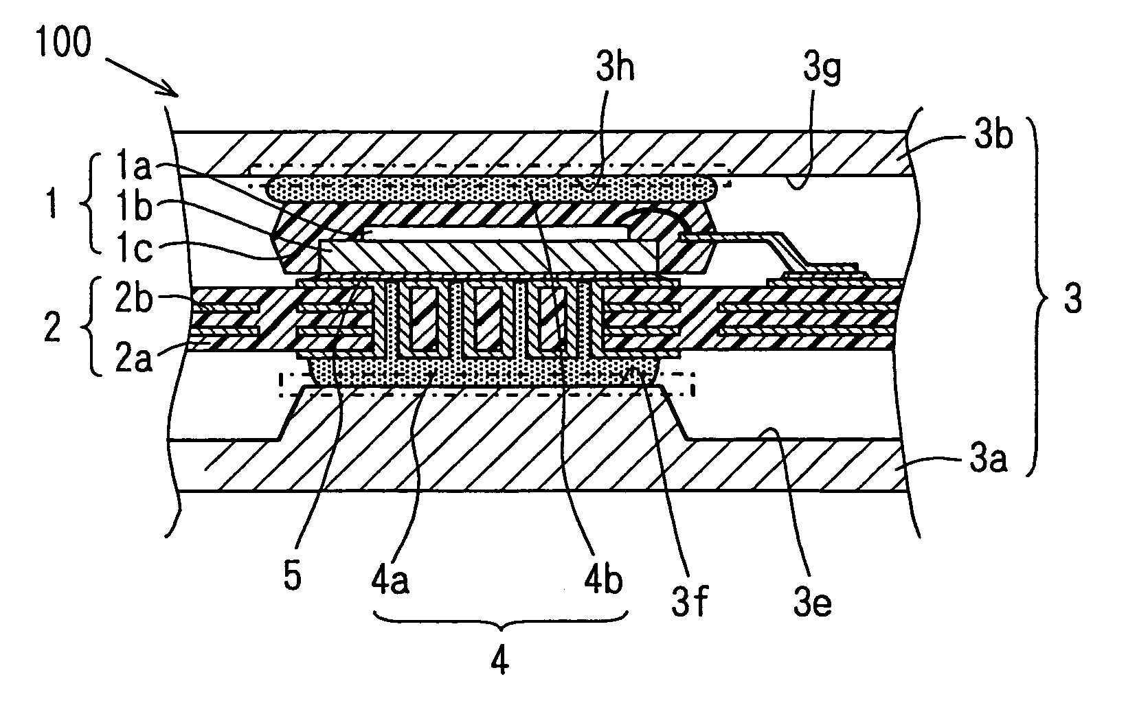
[0028]Referring to FIG. 1, a heat dissipation structure 100 includes a heat-producing electronic component 1, a circuit substrate 2, and a case 3, grease 4, and solder 5. The electronic component 1 is constructed of a semiconductor chip 1a that produces heat, a base 1b,and a resin 1c. The semiconductor chip 1a is mounted on the base 1b and molded with the resin 1c. The substrate 2 is a commonly used multilayer printed circuit substrate having an insulating base 2a and conductive patterns 2b formed in multiple layers.

[0029]The electronic component 1 is mounted on the substrate 2 by soldering the base 1b to the conductive patterns 2b formed on the surface of the substrate 2. The case 3 having thermal conductivity is constructed of a lower case 3a and an upper case 3b for housing the electronic component and the substrate 2. The grease 4 is provided between the lower case 3a and the substrate 2 and between the upper case 3b and the electronic component 1 for transmittin...

Example

Second Embodiment

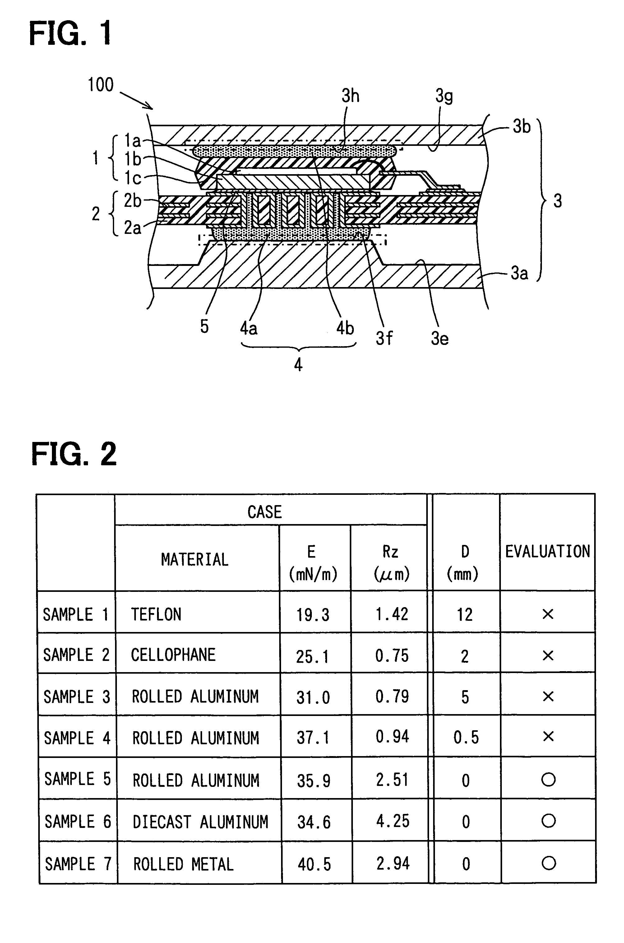
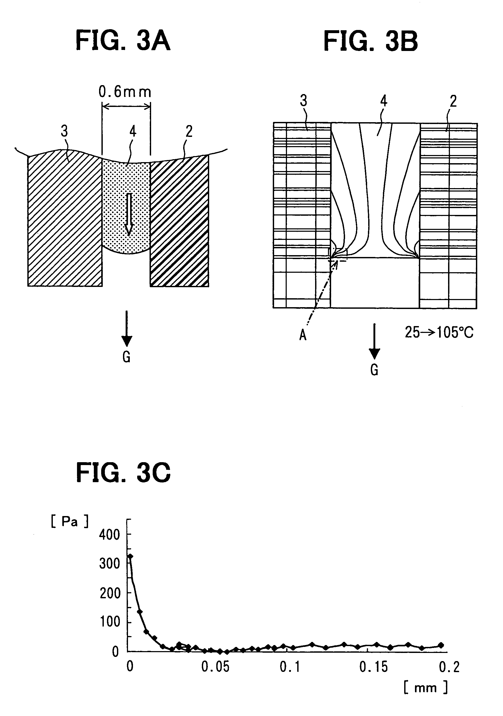
[0039]In a vehicle, circuit substrates are installed in various positions and in conditions that temperature greatly varies. In such conditions, the grease tends to move in the direction of gravitational force due to a cooling cycle. For example, when the temperature changes from 25° C. to 105° C., the grease 4 thermally expands in the direction indicated with a white arrow in FIG. 3A. The thermal stress that is applied to the grease 4 immediately before the grease starts moving is analyzed by the finite element method. The arrangement of the substrate 2, the case 3 and the grease 4 and the conditions of the grease 4 in the analysis are shown in FIG. 3A.

[0040]When the grease 4 thermally expands, shear stresses are produced as shown in FIG. 3B. The stress concentration occurs around edges of the contact surfaces of the grease 4. The contact surfaces are surfaces that contact with the substrate 2 or the case 3. The edge of the contact surface that contacts with the ca...

Example

Third Embodiment

[0050]Referring to FIG. 6A, a case 35 and the substrate 2 have flat contact surfaces 35f and 2f that contact with the grease 4 when the grease 4 is provided between them. The case 35 is made of die-casting aluminum. It is tilted relative to the flat contact surface 2f so that a gap between them is smaller at one end (narrow end) than at the opposite end (broad end). 0.2 ml of the grease 4 is provided in the gap in a manner that its thickness is equal to or less than 1 mm and cooling cycle tests are performed. Temperatures are changes between −40° C. and 125° C. and moving distances D2 of the grease 4 are measured in the cooling cycle tests. The results of the cooling cycle tests are shown in FIG. 6B.

[0051]When the grease 4 is thermally expanded, the thickness of the grease 4 is small at the narrow end and large at the broad end. In general, flow resistance of fluid becomes large as a flow path becomes narrow. Therefore, the grease 4 expands towards the broad end, nam...


PUM

PropertyMeasurementUnit
Thicknessaaaaaaaaaa
Angleaaaaaaaaaa
Viscosityaaaaaaaaaa

Abstract

A heat dissipation structure includes a heat-producing electronic component on a substrate, a thermally conductive case, and grease. The electronic component and the substrate are housed in the case. The grease is provided between the case and the electronic component or the substrate for transmitting heat produced by the electronic component to the case. The case has contact surfaces that contact with the grease. The contact surfaces have free energy equal to or higher than 20 mN/m and roughness equal to or larger than 1.0 μm.

Description

CROSS REFERENCE TO RELATED APPLICATION[0001]This application is based on and incorporates herein by reference Japanese Patent Applications No. 2003-141080 filed on May 19, 2003 and No. 2004-046826 filed on Feb. 23, 2004.FIELD OF THE INVENTION[0002]The present invention relates to a heat dissipation structure for an electronic component.BACKGROUND OF THE INVENTION[0003]In an electronic circuit, heat radiated from a heat producing component such as a power transistor is usually dissipated by a heat sink mounted on the component. However, mounting such a heat sink is a costly process and therefore a heat dissipation structure having the heat sink cannot be reduced in cost. Furthermore, the heat sink cannot be used for dissipating heat produced by the surface mount device.[0004]To solve the problems, a case for housing an electronic component and a circuit substrate is used as a heat sink and the substrate is thermally coupled with the case via a heat dissipation member. Heat dissipatio...

Claims


Application Information

Patent Timeline
IPC IPC(8): G06F1/20H01L23/36H01L23/367H01L23/42H05K1/02H05K3/42H05K7/20
CPCH01L23/3677H01L23/42H05K1/0206H01L2224/48091H01L2224/48247H01L2924/01025H01L24/48H05K2201/09054H05K2201/0959H05K2201/10166H05K3/429H01L2924/00014H01L2224/05599H01L2224/45099H01L2224/85399H01L2924/181Y10T428/31681H01L2224/45015H01L2924/207H01L2224/43H01L2924/00012
Inventor ITO, KAZUTOSHIOGURI, TAKAMASAMIZUTANI, AKIHIRO
Owner DENSO CORP
Why Eureka
Try Eureka