Optical transmission device and optical transmission system

a transmission device and optical transmission technology, applied in the field of optical transmission devices and optical transmission systems, can solve the problems of system lack of expansibility, deterioration of electric characteristics, and enlargement of the circuitry of these converting sections, so as to improve system expansibility and communication quality, reduce size, and improve the effect of system expansibility

Inactive Publication Date: 2006-06-06
FUJITSU LTD
View PDF17 Cites 4 Cited by
  • Summary
  • Abstract
  • Description
  • Claims
  • Application Information

AI Technical Summary

Benefits of technology

[0016]The present invention was created in view of the above circumstances, and an object thereof is to provide an optical transmission device in which optical signal switching is performed to allow the device to be reduced in size and also which is capable of efficient recovery from fault, thereby improving the system expansibility and the communication quality.
[0017]Another object of the present invention is to provide an optical transmission system in which optical signal switching is performed to allow each of devices constituting the system to be reduced in size and also which is capable of efficient recovery from fault, thereby improving the system expansibility and the communication quality.

Problems solved by technology

A problem also arises in that increase in transmission speed entails enlargement of the scale of the circuitry of these converting sections.
In such cases, interface signals on the backboard or in the unit also increase, giving rise to a problem that the electric characteristics deteriorate due to crosstalk or the like.
Thus, where a terminal office is connected to the node, no line switching is performed with respect to the terminal office, so that the system lacks expansibility.
Also, since neither fault information extraction process nor device status information setting function is available, a problem arises in that a faulty spot cannot be located.

Method used


Image

  • Optical transmission device and optical transmission system
  • Optical transmission device and optical transmission system
  • Optical transmission device and optical transmission system

Examples


Embodiment Construction

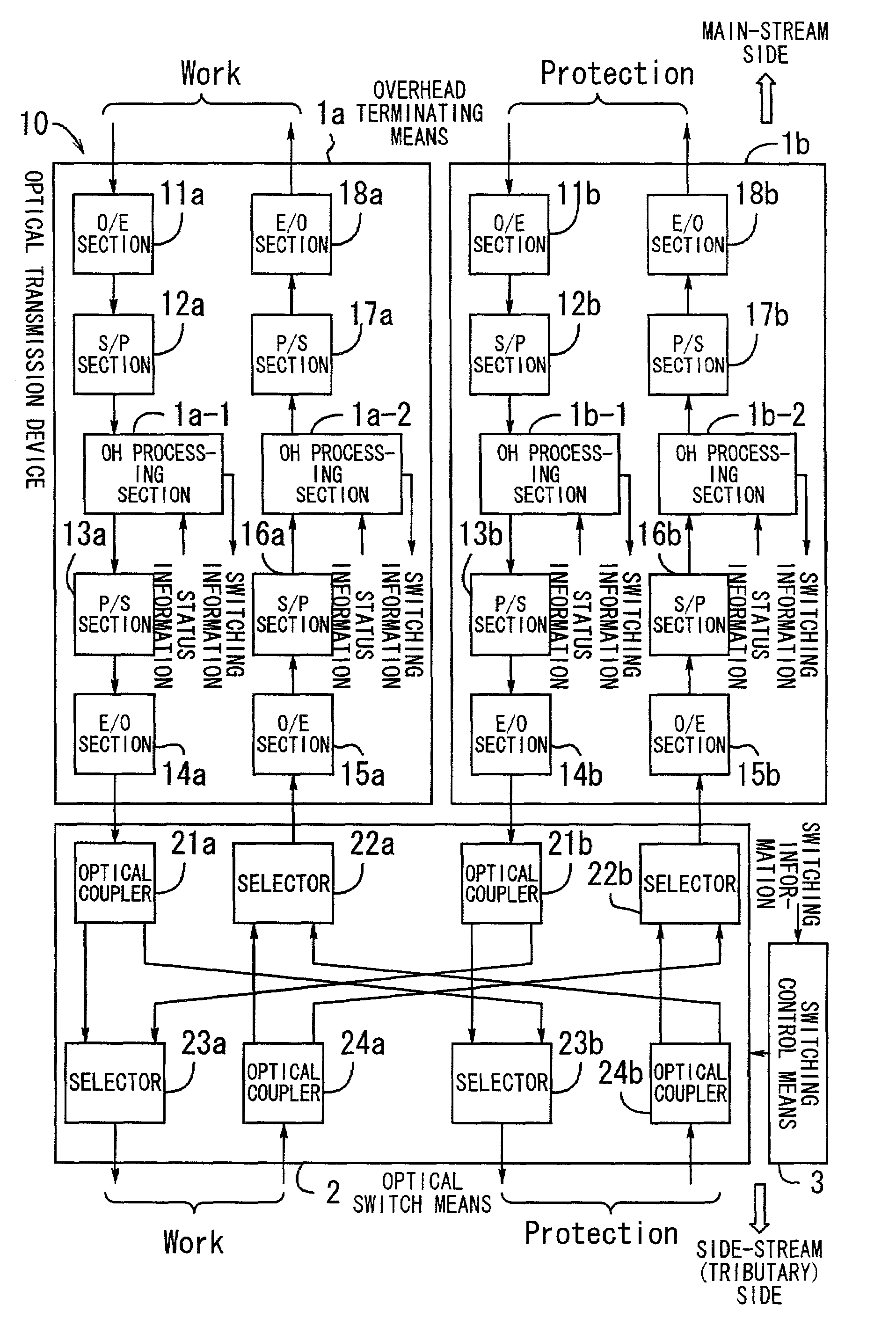
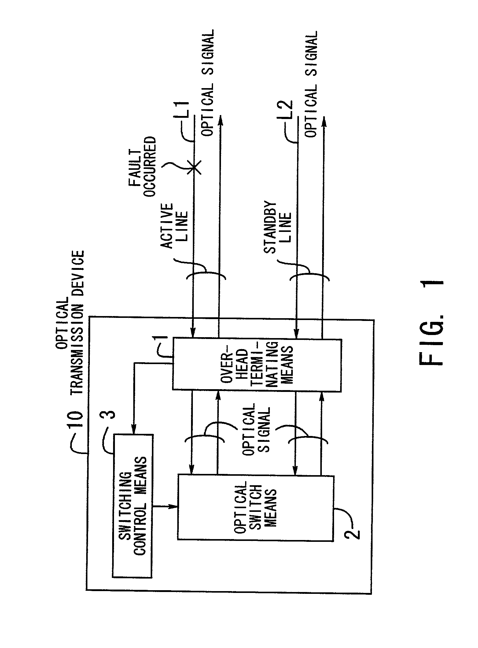
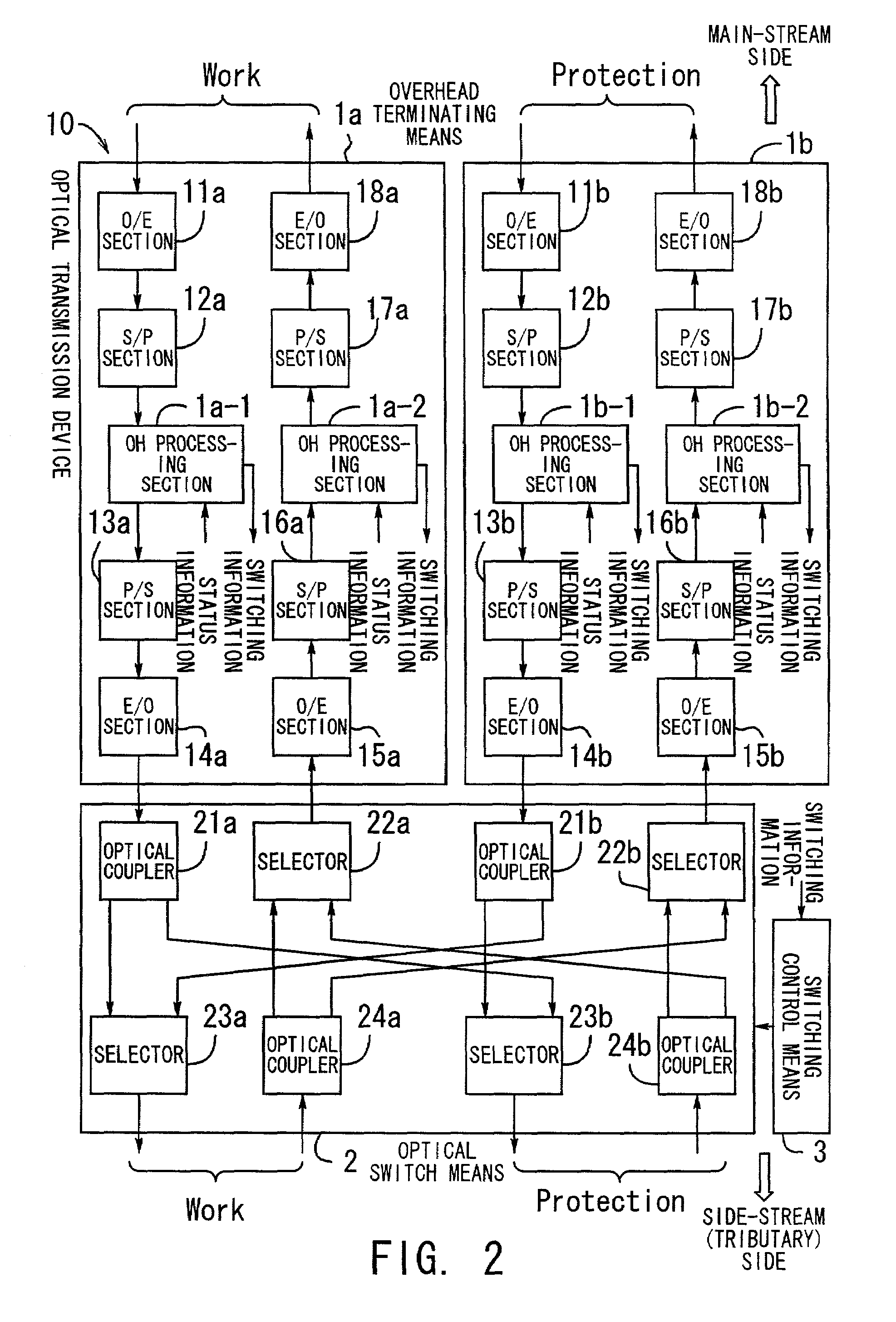
[0036]Embodiments of the present invention will be hereinafter described with reference to the drawings. FIG. 1 illustrates the principle of an optical transmission device according to the present invention. The optical transmission device 10 controls the transmission of optical signals.

[0037]Overhead terminating means 1 converts an optical signal to an electric signal. Also, the overhead terminating means extracts fault information about fault on the transmission line as well as status information of other devices (information about internal fault etc. of the other devices) from the electric signal, and sets status information of its own device. This process carried out by the overhead terminating means is hereinafter referred to as overhead process.

[0038]The overhead terminating means 1 outputs the optical signal received from outside to optical switch means 2, and also outputs the optical signal received from the optical switch means 2 to outside.

[0039]The optical switch means 2 ...


PUM


Abstract

An optical transmission device in which optical signal switching is performed to allow the device to be reduced in size and also which is capable of efficient recovery from fault, thereby improving system expansibility and communication quality. Overhead terminating section converts an optical signal to an electric signal and performs an overhead process including extraction of fault information and setting of status information. Optical switch section performs a process of switching the optical signal between active and standby lines, and switching control section provides a switching command to the optical switch section in accordance with the fault information.

Description

[0001]This application is a continuation of international application number PCTJP 99 / 06269, filed Nov. 10, 1999.BACKGROUND OF THE INVENTION[0002](1) Field of the Invention[0003]The present invention relates to an optical transmission device and an optical transmission system, and more particularly, to an optical transmission device for controlling the transmission of optical signals and to an optical transmission system for controlling the transmission of optical signals over a ring network.[0004](2) Description of the Related Art[0005]Optical communication network technology is a core technology for constructing the infrastructure of information communication networks and is undergoing rapid development for the present-day information-oriented society in which highly advanced, wider-coverage services are demanded. Also, investigation is being made into network topologies that suit various fields of applications of optical communications.[0006]FIG. 14 illustrates an optical communi...

Claims


Application Information

Patent Timeline
Patent Type & Authority Patents(United States)
IPC IPC(8): H04B10/08H04B10/032H04J14/02H04Q11/00
CPCH04B10/032H04J14/0227H04J14/0283H04J14/0295H04J14/0245H04J14/0249H04Q11/0062H04Q2011/0081H04Q2011/0084
Inventor KOYANO, HIDEAKIKOBAYASHI, MASATOTAKAIWA, KAZUMAROHIRAIZUMI, MAKITAKAYASU, AKIO
Owner FUJITSU LTD
Why Eureka
Try Eureka