Real-time control process for a controller of an industrial technical process, and a real-time operating process for a computing device

a technology of industrial technology and control process, applied in the direction of electric controllers, program control, electric programme control, etc., can solve the problem of complex process of distributing a new version of control software, and achieve the effect of flexible cooperation between logic units and computing devices

Active Publication Date: 2006-06-06
SIEMENS AG
View PDF8 Cites 7 Cited by
  • Summary
  • Abstract
  • Description
  • Claims
  • Application Information

AI Technical Summary

Benefits of technology

[0014]Accordingly, the industrial technical process, the measuring units and controllers and the logic unit can be separate from the computing device, which makes it possible to update and / or improve the computing device and / or the real-time core without having to replace the logic unit on-site, because the measured state signals and the control signals that are transmitted to the process remain completely unchanged, and the computing power for determining the control signals need no longer be provided on-site. Moreover, a real-time core that operates the computing device also needs no longer be distributed.
[0021]According to another advantageous embodiment, a particularly flexible programming of the logic unit can be achieved if before executing the process, the logic unit receives a real-time portion of a computer program to be executed by the logic unit.
[0023]According to yet another advantageous embodiment, the cooperation between the logic unit and computing device can be made more flexible if before executing the process, the logic unit transmits via the transmission medium to the computing device a control program to be executed by the computing device. Alternatively, the control program can also be stored in advance in the computing device. Alternatively, the logic unit can also access a control program stored in the computing device.

Problems solved by technology

It can also be a complex process to distribute a new version of control software, in particular the real-time core, to all installed controllers.

Method used


Image

  • Real-time control process for a controller of an industrial technical process, and a real-time operating process for a computing device
  • Real-time control process for a controller of an industrial technical process, and a real-time operating process for a computing device
  • Real-time control process for a controller of an industrial technical process, and a real-time operating process for a computing device

Examples


Embodiment Construction

[0031]Throughout all the Figures, same or corresponding elements are generally indicated by same reference numerals. These depicted embodiments are to be understood as illustrative of the invention and not as limiting in any way. It should also be understood that the drawings are not necessarily to scale and that the embodiments are sometimes illustrated by graphic symbols, phantom lines, diagrammatic representations and fragmentary views. In certain instances, details which are not necessary for an understanding of the present invention or which render other details difficult to perceive may have been omitted.

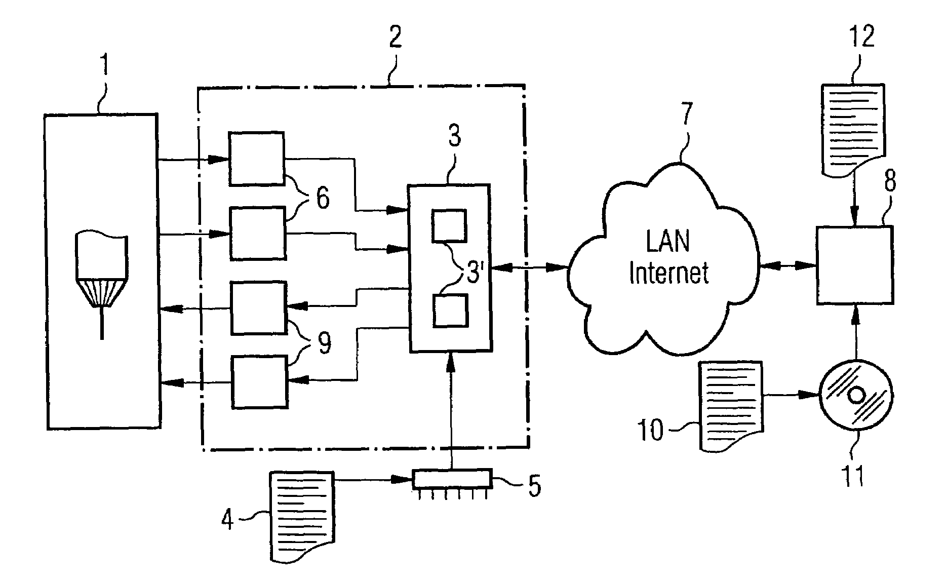
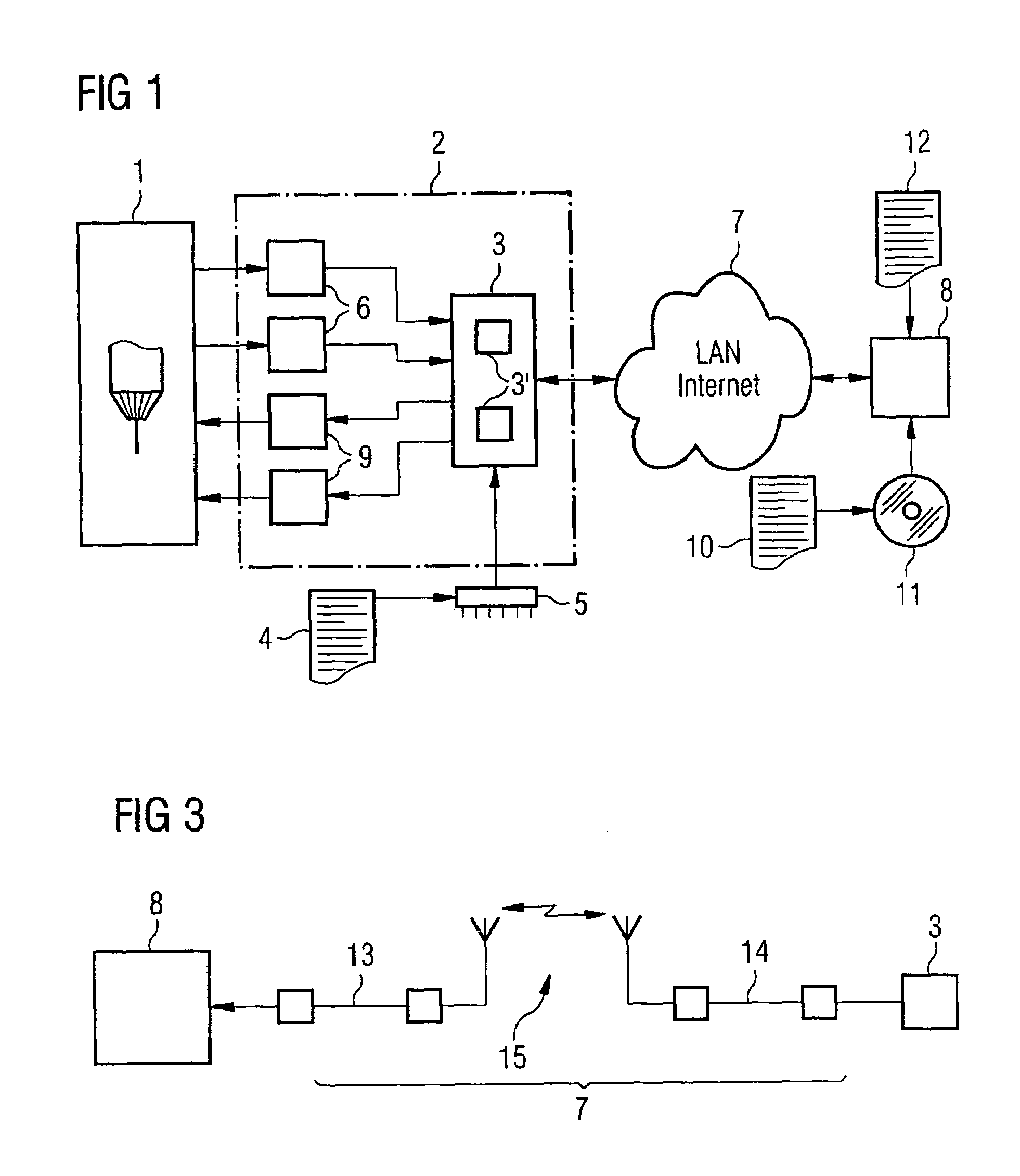
[0032]Turning now to the drawing, and in particular to FIG. 1, there is shown an industrial technical process 1 that is controlled by a controller 2. The industrial technical process 1 in the depicted exemplary embodiment is a production process 1, such as a machining process 1 of a machine tool, as indicated in FIG. 1 by the schematic illustration of a drill chuck and a drill...


PUM


Abstract

Measuring units measure state signals of an industrial technical process. The entirety of the state signals represents an image of the process. The measuring units transmit the state signals to a common logic unit which transmits the image of the process at least partially via a transmission medium to a computing device. The computing device executes a control program to determine at least a portion of the control state for the process and transmits the portion to the logic unit via the transmission medium. The control state includes control signals for a number of control devices. The logic unit transmits to each of the control devices the control signals intended for the respective control device. The control devices affect the process accordingly. The above steps are repeatedly executed in real-time with a cycle time in a range of milliseconds or less.

Description

CROSS-REFERENCES TO RELATED APPLICATIONS[0001]This application claims the priority of German Patent Application, Serial No. 103 40 403.1, filed Sep. 2, 2003, pursuant to 35 U.S.C. 119(a)–(d), the disclosure of which is incorporated herein by reference.BACKGROUND OF THE INVENTION[0002]The present invention relates to a real-time control process for a controller of an industrial technical process, and to a real-time operating process for a computing device.[0003]Nothing in the following discussion of the state of the art is to be construed as an admission of prior art.[0004]Controllers for industrial technical processes are known in the art. Depending on the particular application, these controllers can be implemented as numerical controllers (CNC) or as stored-program controllers (SPS). These controllers operate with a cycle time in the millisecond range or below, and typically execute the following steps:[0005]A number of measuring units measures state signals of the process, whereb...

Claims


Application Information

Patent Timeline
Patent Type & Authority Patents(United States)
IPC IPC(8): G05B11/01G05B19/05
CPCG05B19/052
Inventor DOLANSKY, STEFAN
Owner SIEMENS AG
Why Eureka
Try Eureka