Deployable spacecraft mount for electric propulsion

a technology of electric propulsion and spacecraft, which is applied in the field of spacecraft mounts for electric propulsion, can solve the problems of reducing the life of spacecraft by years, and the current spacecraft employing solar panel concentrators may also experience negative effects of xips plume interaction, so as to achieve the effect of reducing the known deleterious effects of their plume field

Inactive Publication Date: 2006-06-13
THE BOEING CO
View PDF8 Cites 27 Cited by
  • Summary
  • Abstract
  • Description
  • Claims
  • Application Information

AI Technical Summary

Benefits of technology

[0011]The present invention addresses the industry-acknowledged difficulty of integrating electric propulsion thrusters, e.g. Hall effect thrusters (non-gridded electric thrusters), on spacecraft, in a benign fashion. To fully leverage the mass savings that Hall thrusters can yield, they must also be positioned to fire through the spacecraft center of gravity. The application of the present invention builds upon some existing innovations for deployable radiators and ion thrusters. Described in this disclosure is a apparatus and method where electric thrusters are located (depicted as a Hall effect thruster) on a spacecraft to mitigate the known deleterious effects of their plume field on subsystems, including deployed antennae, solar panels and radiator surfaces. With the development of high thrust electric propulsion systems and their planned placement on diverse programs, such as Lockheed's AEHF offering and ESA's XEUS spacecraft, the present invention improves upon conventional spacecraft designs that implement these thrusters.
[0014]Established trends for the increased thermal dissipation of high power payloads portend the use of deployable radiator panels. Examples of high power and high mass spacecraft design problems, that can only be resolved with the incorporation of electric propulsion, already exist and all electric propulsion spacecraft have been proposed in numerous industry studies. By coupling the location of electric thrusters on deployable radiators, these high mass payloads with increased thermal demands can coincidentally provide a solution for both plume interaction while facilitating optimal firings through the spacecraft center of gravity.
[0015]Embodiments of the present invention can comprise a configuration that employs the design concept of a flight-proven spacecraft model utilizing deployable radiators to provide an electric thruster mounting location more removed from the spacecraft body and critical antenna surfaces, such as mesh and shaped reflectors. The negative effect of plume interaction is greatly reduced or eliminated by the increased displacement from the spacecraft body surfaces and the decreased number of particle intercept angles with these surfaces. Current deployed radiator spacecraft designs can be implemented with outboard thruster mounting locations approximately 6 to 8 feet away from the spacecraft body. As a one time event, utilizing the deploying radiator as a supporting structural platform for the electric thruster makes this an ideal location.
[0017]A typical embodiment of the invention includes a spacecraft body, a deployable element having at least two basic positions including a compact stowed position and a deployed position of the element and an electric thruster disposed on the deployable element where the electric thruster is disposed to mitigate negative plume effects in the deployed position that would be present in stowed position. The deployable element can comprise a deployable radiator for transferring excess heat energy from the spacecraft body. Often, the electric thruster is disposed on an outboard end of the deployable element.

Problems solved by technology

The effects of contamination from ion engines can reduce spacecraft life by years.
Additionally current spacecraft employing solar panel concentrators may also experience negative effects from XIPS plume interaction.

Method used


Image

  • Deployable spacecraft mount for electric propulsion
  • Deployable spacecraft mount for electric propulsion
  • Deployable spacecraft mount for electric propulsion

Examples


Embodiment Construction

[0030]In the following description of the preferred embodiment, reference is made to the accompanying drawings which form a part hereof, and in which is shown by way of illustration specific embodiments in which the invention may be practiced. It is to be understood that other embodiments may be utilized and structural changes may be made without departing from the scope of the present invention.

[0031]1.0 Deployable Spacecraft Elements

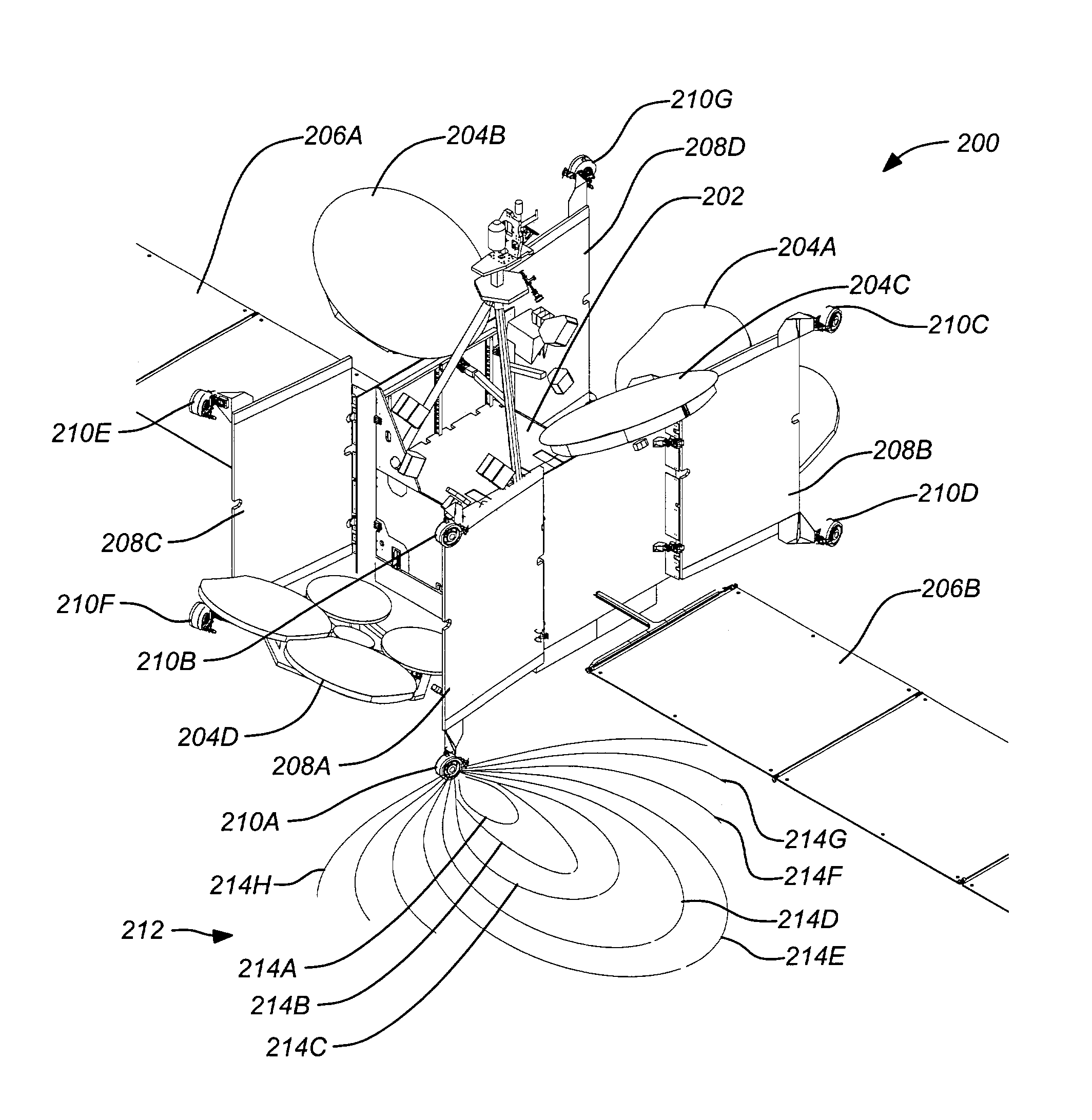
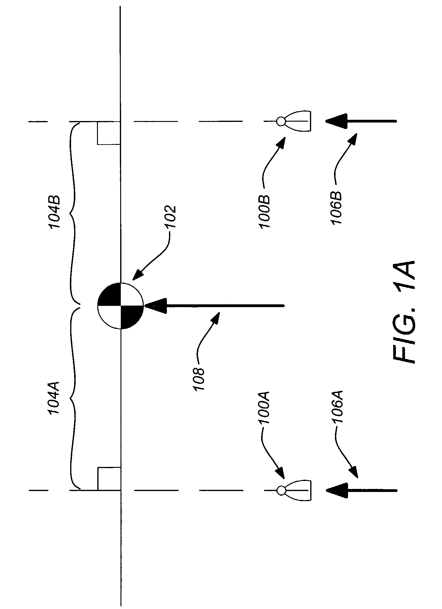
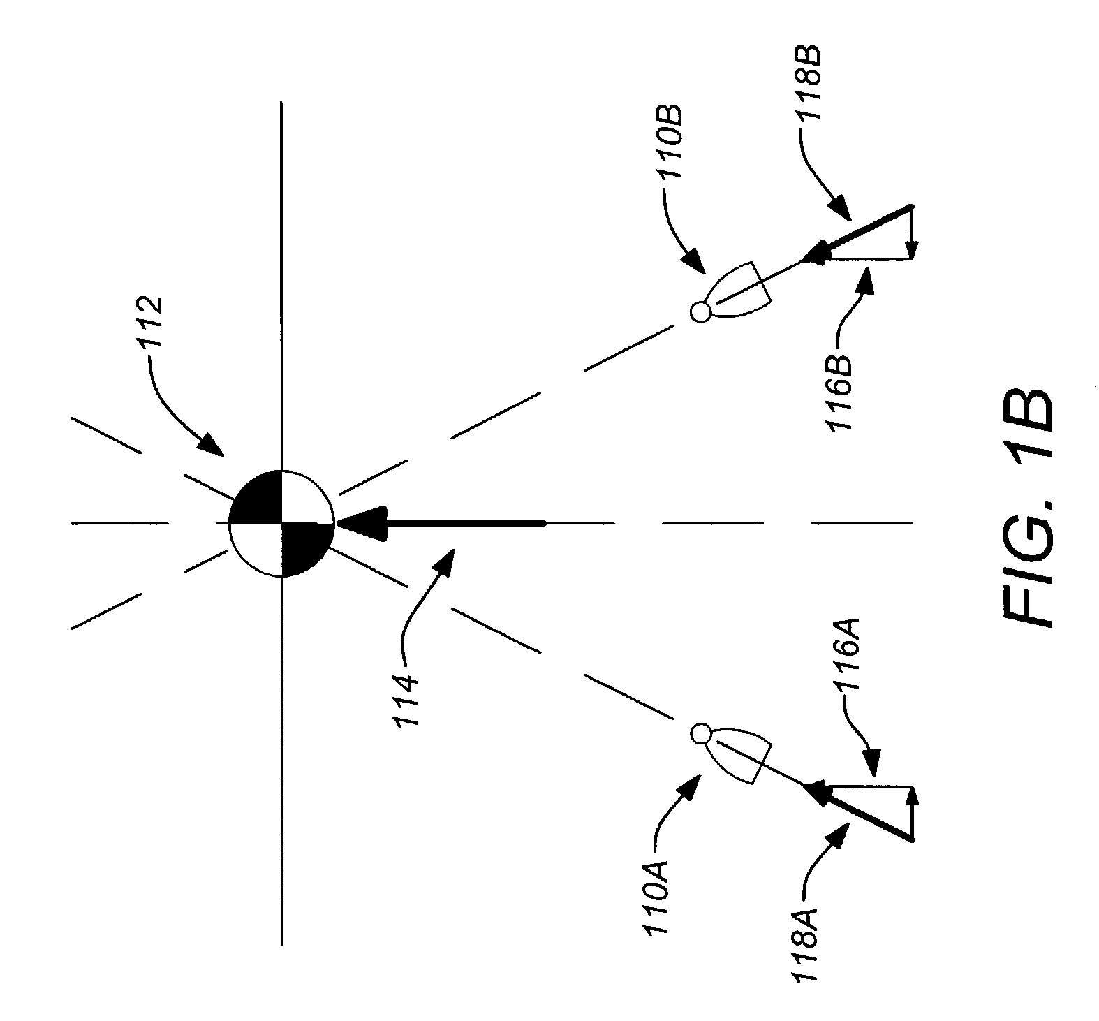
[0032]As discussed above, obtaining adequate thruster offset is important to mitigate negative plume effects while maintaining acceptable thruster efficiency. Typically, spacecraft include a main body which provides the foundational platform for the spacecraft. To fit within a compact envelope for transport, e.g., within a launch vehicle shroud, many spacecraft elements (e.g., appendages and / or subsystems) can be designed to be deployable. At various stages during the launch the various elements are deployed to enable complete spacecraft functionality ...


PUM


Abstract

An apparatus and method including a deployable spacecraft mount for electric propulsion is disclosed. A typical apparatus includes a spacecraft body, a deployable element having at least two basic positions including a compact stowed position and a deployed position of the element and an electric thruster disposed on the deployable element where the electric thruster is disposed to mitigate negative plume effects in the deployed position that would be present in stowed position. The deployable element can be a radiator and can optionally be disposed on a second deployable payload module. Further, deployable elements can be selective deployed such that some electric thrusters can be used to assist in transfer orbit while undeployed elements help retain heat.

Description

BACKGROUND OF THE INVENTION[0001]1. Field of the Invention[0002]The present invention relates to apparatuses and methods for the implementation of electric propulsion in spacecraft. Particularly, the present invention relates to mounting solutions for Hall effect thrusters to mitigate harmful thruster plume effects.[0003]2. Description of the Related Art[0004]In recent years, electric propulsion systems, e.g. xenon ion propulsion systems, have been implemented in spacecraft. Current high power applications of this thruster now make it possible to accomplish both orbit raising and station keeping. This combination may yield an all electric spacecraft with a propulsion system several times lighter than a chemical system. However, electric thruster plumes are typically wide and avoiding spacecraft structure can be problematic. Particularly, Hall effect electric thrusters (operating without front grids) are known to have widely dispersed plumes resulting in a significant potential for n...

Claims


Application Information

Patent Timeline
Patent Type & Authority Patents(United States)
IPC IPC(8): B64G1/26B64G1/00B64G1/22B64G1/40B64G1/50
CPCB64G1/405B64G1/007B64G1/222B64G1/503B64G1/26B64G1/2427
Inventor KELLBERG, CHRISTIAN J.
Owner THE BOEING CO
Why Eureka
Try Eureka