Horizontal compressor end cap with a terminal, a visually transparent member, and a heater well mounted on the end cap projection

a compressor and end cap technology, applied in the direction of positive displacement liquid engines, pumping, lighting and heating apparatus, etc., can solve the problems of reducing limiting the amount of oil available to compressor components, and increasing the complexity of assembly and thus the cost of assembly of compressors, so as to reduce the potential for leakage, improve the reliability of compressors, and reduce scrap

Inactive Publication Date: 2006-06-13
TECUMSEH PROD CO
View PDF39 Cites 21 Cited by
  • Summary
  • Abstract
  • Description
  • Claims
  • Application Information

AI Technical Summary

Benefits of technology

[0015]One advantage of the present invention is that it avoids the need to place component mounting surfaces and holes in a cylindrical housing body. This reduces the potential for leaks and thereby improves the compressor reliability. This also reduces the possibility of cracking and other damage to the cylindrical housing body during manufacture thereby reducing scrap and promoting manufacturing efficiency.
[0016]Another advantage of the present invention is that assembly of the compressor is simplified by mounting these components to the housing in a single assembly and welding operation, thus reducing the cost of manufacturing of the compressor. Additionally, fewer a

Problems solved by technology

Upon startup of the compressor, the temperature and pressure increase and the mixture is agitated, causing the mixture to foam, limiting the amount of oil available to the compressor components.
Additionally, the viscosity of the oil increases as the temperature in the compressor housing decreases, causing the oil to resist flowing easily upon startup.
A problem with this type of housing construction includes mounting the components in different portions of the housing.
Multiple assembly and welding operations are then required on different housing portions, which increases the complexity of assembly and thus the cost of assembly of the compressor.
For example, if above-described apertured

Method used


Image

  • Horizontal compressor end cap with a terminal, a visually transparent member, and a heater well mounted on the end cap projection
  • Horizontal compressor end cap with a terminal, a visually transparent member, and a heater well mounted on the end cap projection
  • Horizontal compressor end cap with a terminal, a visually transparent member, and a heater well mounted on the end cap projection

Examples


Embodiment Construction

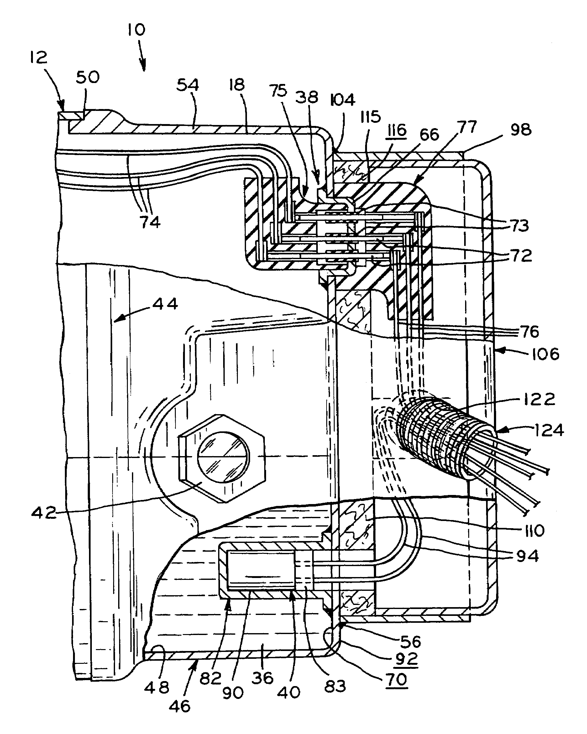
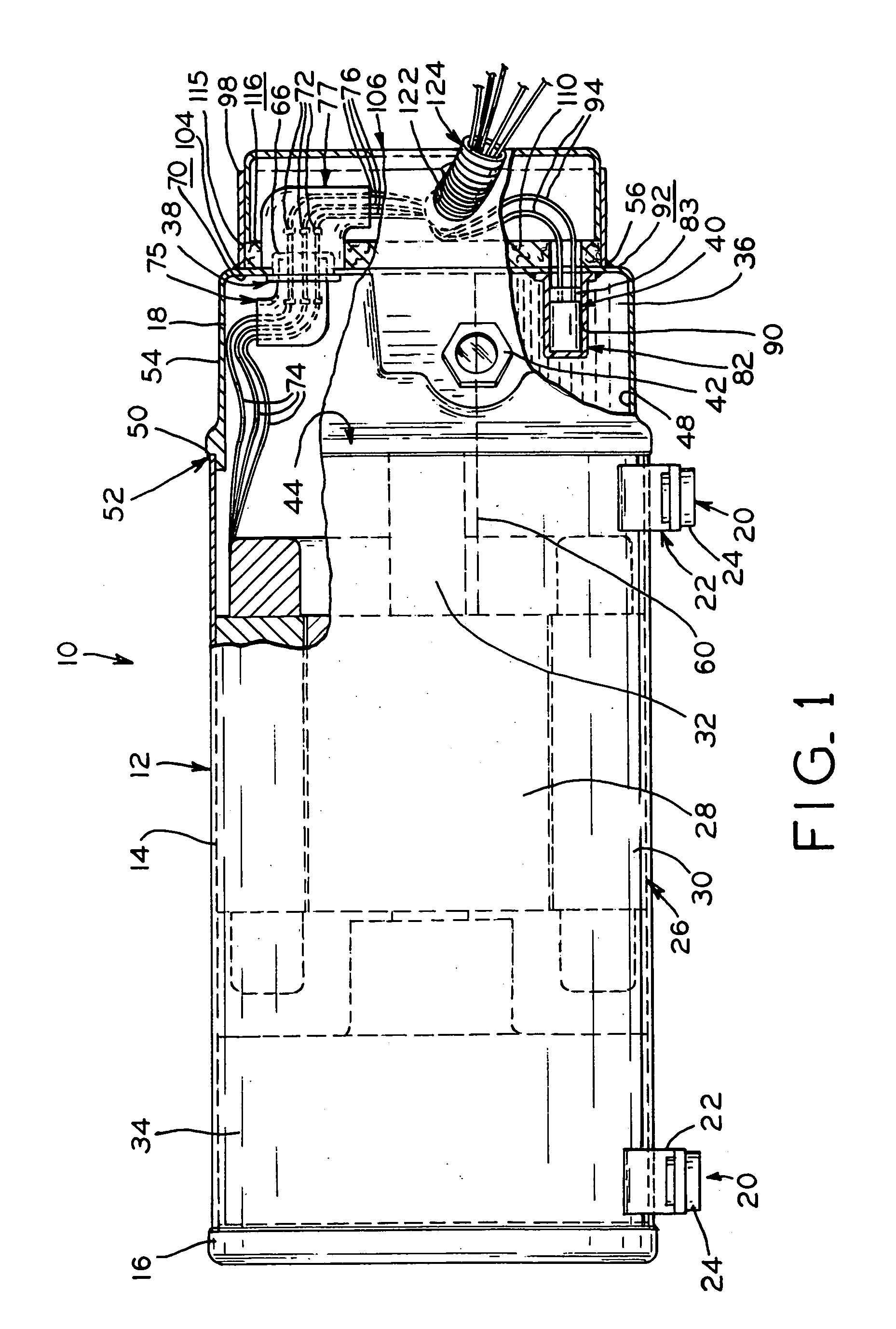
[0024]Referring to FIG. 1, compressor 10 is a substantially horizontal hermetic compressor including housing 12. Housing 12 includes substantially cylindrical main body portion 14 having end caps 16 and 18 mounted thereto by any suitable method including welding, brazing, or the like. Housing 12 may be constructed from any suitable metal including steel or the like, able to withstand the generally well known operating conditions of prior compressors. The housing end caps may be formed by stamping, and the cylindrical main portion may be roll formed and welded, for example. Alternatively, end cap 16 may be integrally formed with the cylindrical main portion by a deep-drawing operation, for example.

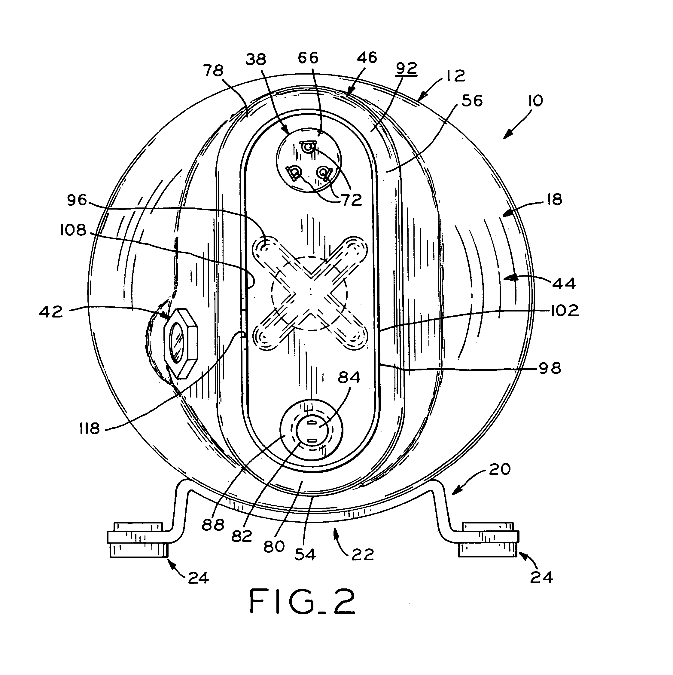
[0025]Referring to FIGS. 1 and 2, compressor 10 is oriented in a substantially horizontal position being supported on mounts 20. Mounts 20 each include support portion 22 shaped to engage a portion of the outer surface of housing main body portion 14. Feet 24 are integrally formed with each...


PUM


Abstract

A substantially horizontal compressor including a housing having a main body portion with an open end. An end cap is secured to the main body portion with the end cap being provided with a plurality of apertures. The hermetic terminal body of the compressor is sealably fitted into one of the plurality of apertures located in the end cap. One of the apertures is sealably fitted with a heater well in which a substantially cylindrical heater element is removably received. A third aperture may be provided in the end cap in which a sight glass is sealably secured for checking the oil level in the oil sump. An indentation is formed in the end cap to increase the rigidity of the end cap. The proximity of the terminal assembly and heater well allows the wiring therefor to be part of the same wiring harness.

Description

CROSS REFERENCE TO RELATED APPLICATIONS[0001]This application claims priority under 35 U.S.C. 119(e) of U.S. provisional patent application Ser. No. 60 / 432,190 filed on Dec. 10, 2002 entitled HORIZONTAL COMPRESSOR END CAP the disclosure of which is hereby incorporated by reference.BACKGROUND OF THE INVENTION[0002]The present invention relates to substantially horizontal hermetic compressors, and more particularly to the compressor housings and the mounting of components such as the terminal assembly, a sight glass, and a heater in the housing.[0003]In general, the housing of a substantially horizontal hermetic compressor may include a substantially cylindrical main body portion and a pair of end caps mounted to each end of the main body portion. Alternatively, one of the end caps may be integrally formed with the main body portion. A motor and a compression mechanism are mounted in the main body portion. The motor has a plurality of lead wires electrically connected thereto. The lea...

Claims


Application Information

Patent Timeline
IPC IPC(8): F04B17/02F01C21/10F04B39/12F04C23/00F04C29/00F04C29/02
CPCF01C21/10F04B39/12F04C29/0085F04C29/02F04C23/008F04C2240/803Y10S417/902
Inventor HALLER, DAVID K.SKINNER, ROBIN G.
Owner TECUMSEH PROD CO
Why Eureka
Try Eureka