Cell equalizing circuit

a cell equalization and circuit technology, applied in the field of electric circuits, can solve the problems of reducing the overall battery performance, reducing the remaining capacity of cells, and further use of batteries, so as to maximize the available capacity of all cells, prevent cell damage, and maximize the effect of battery li

Inactive Publication Date: 2006-06-13
H2EYE INT
View PDF8 Cites 68 Cited by
  • Summary
  • Abstract
  • Description
  • Claims
  • Application Information

AI Technical Summary

Benefits of technology

[0012]By allowing an effective transfer of current between received cells, the received cell voltages can be maintained equal, either during charging or discharging of the cells. The electric circuit loaded with cells thus removes any disparity in voltage between the cells. Cells which are under-voltage are charged by the other cells and cells which are over-voltage are discharged by the other cells. The circuit thus ensures that an individual cell in a battery is not inadvertently discharged below its deep-discharge threshold or charged above its over-charge threshold. In addition, during discharge, maximum utilization of the available capacity of all cells in the battery is ensured.
[0013]For rechargeable cells, the invention thus maximizes battery life in terms of numbers of charge / discharge cycles by preventing cell damage. For rechargeable or non-rechargeable cells, whether rechargeable or not, the invention maximizes battery life within a single discharge by ensuring even discharge of all cells within the battery.
[0014]Alternatively, the circuit of the invention may be viewed as a simpler and more elegant solution than providing a circuit which individually monitors the voltage of each of a number of cells during charge or discharge.
[0016]The inductive coupling may be conveniently implemented with transformer windings. The windings are preferably wound around a common core to increase coupling efficiency. The transformer windings may further comprise a center-tap between two end-taps with alternate phases of the AC voltages applied between the center-tap and one or other of the end-taps. This allows for efficient inductive coupling of the DC to AC converters using readily available technology.
[0018]In embodiments of the invention, each of the DC-to-AC converters comprises a first switch responsive to a first control signal for providing a first polarity of the AC voltage and a second switch responsive to a second control signal for providing a second polarity of the AC voltage. By employing a center-tapped transformer and appropriate switching of the switches, effective DC to AC conversion can be achieved simply and with a minimum number of switching components. The first and second switches may be field effect transistors since these allow rapid switching with only a modest voltage drop when in conduction. In operation, the control signals are provided such that a time delay occurs between activation of the first and second switches. This helps to ensures that the two windings of each of the center-tapped transformer windings do not both conduct at the same time.

Problems solved by technology

Differences in the charging and discharging characteristics of cells in a battery make it difficult to properly manage the charging and discharging of individual cell, this can significantly reduce the overall battery performance.
If 3.0V represents the deep-discharge threshold, further use of the battery will have a deleterious effect on cell 2A.
However, if discharge is stopped to protect cell 2A, the remaining capacity of cells 2B-H is unused, and the battery requires recharging before its total useful capacity has been exhausted.
If 4.2V represents the over-charge threshold, further charging of the battery will have a deleterious effect on cell 2A.
However, if charging is stopped to protect cell 2A from over-charge, the battery voltage is limited to 29.2V, so reducing its capacity during subsequent use.

Method used


Image

  • Cell equalizing circuit
  • Cell equalizing circuit
  • Cell equalizing circuit

Examples


Embodiment Construction

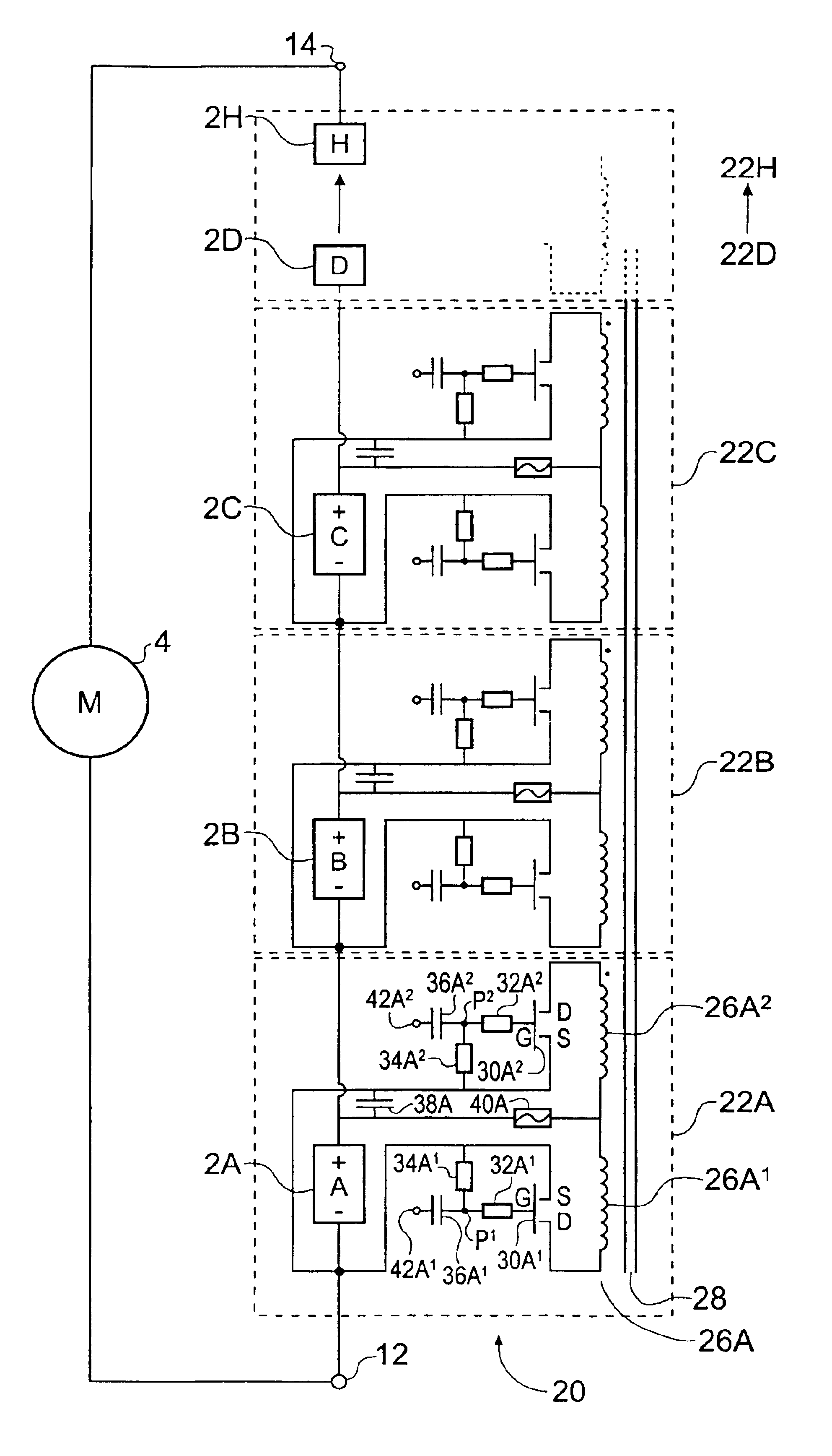
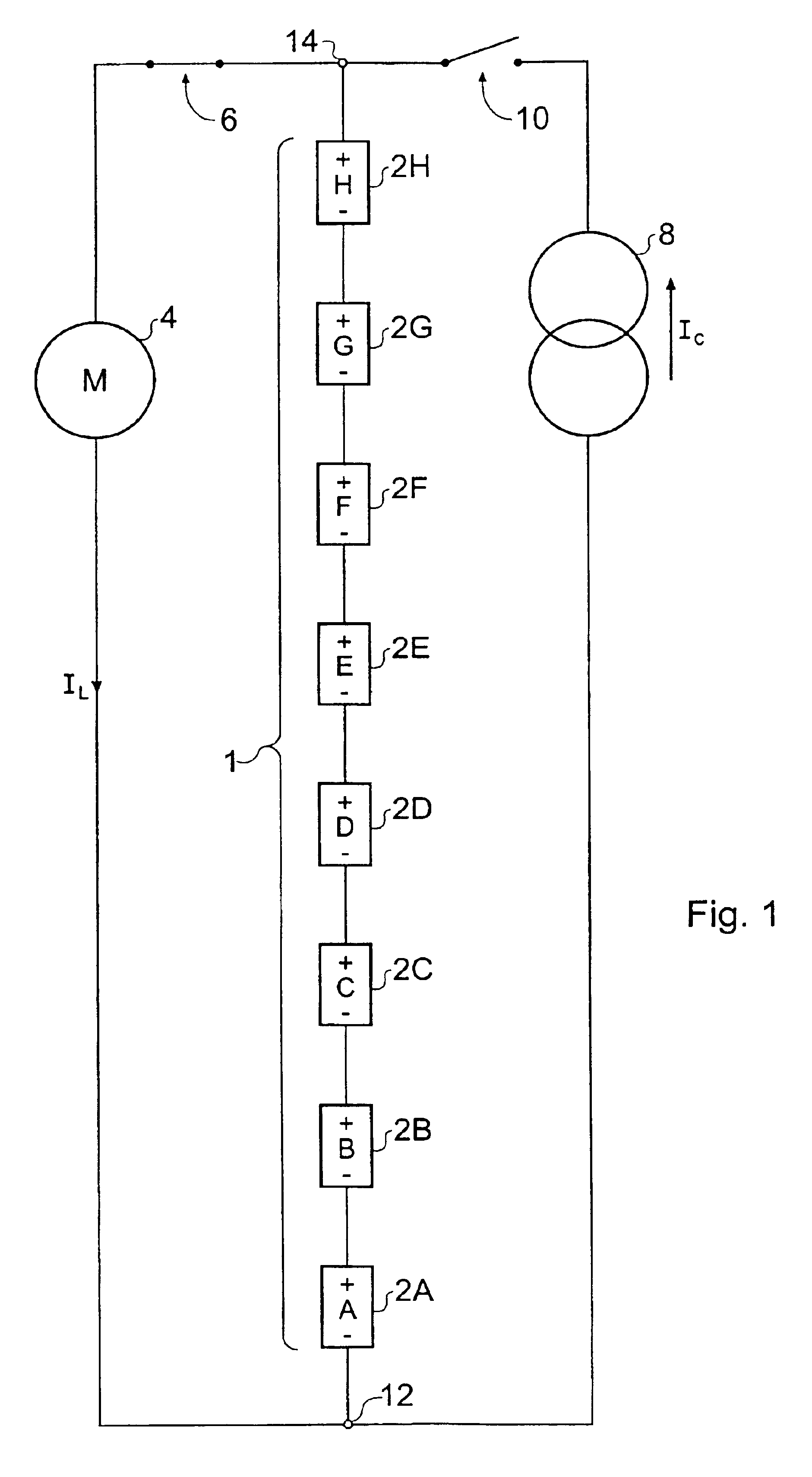
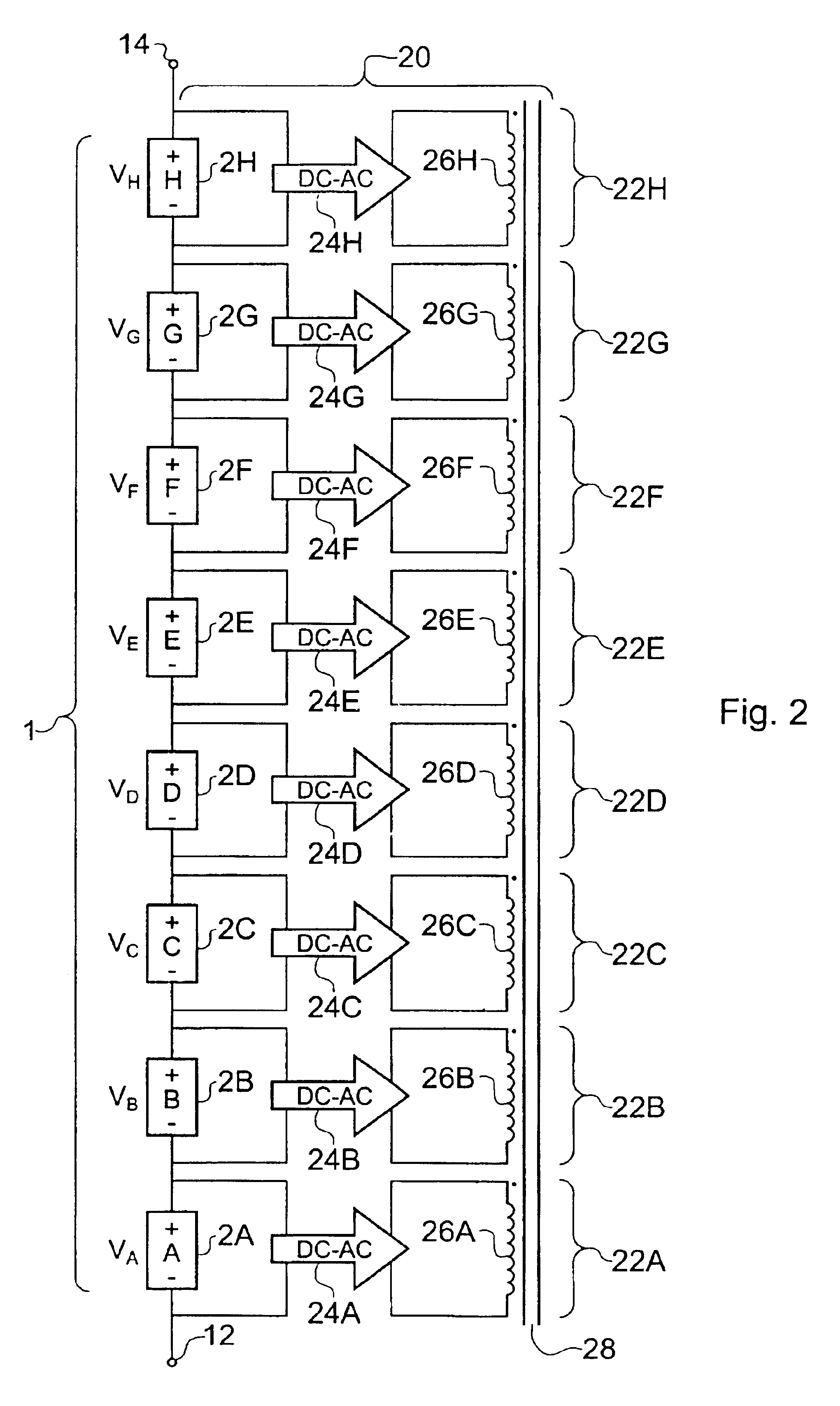
[0035]FIG. 2 is a diagram schematically showing the underlying principle of an equalizing circuit 20 for equalizing cell voltages of eight cells 2A-H according to an embodiment of the invention. The cells 2A-H form a battery 1 with a cathode 12 and an anode 14. These features are similar to and will be understood from the description of the correspondingly numbered features seen in FIG. 1. The equalizing circuit 20 includes eight similar circuit modules 22A-H and a single ferrite core 28.

[0036]The circuit module 22A includes a direct current to alternating current (DC to AC) converter 24A and an inductive winding 26A. The cell 2A is connected to an input of the DC to AC converter and the DC to AC converter is operable to convert a DC cell voltage VDCA of the cell 2A to an AC voltage VACA. The AC voltage VACA has an amplitude dependent on the DC voltage VDCA and a frequency f. The AC voltage VACA is coupled to the inductive winding 26A as indicated in the figure.

[0037]The circuit mod...


PUM


Abstract

An electric circuit for equalizing voltages between serially arranged cells. The circuit is operable to generate AC voltages at amplitudes dependent on the DC voltages of the received cells. The AC voltages are all connected to an inductive coupling circuit. The inductive coupling allows higher-voltage cells to induce a recharging current flow in lower voltage cells and so equalize the cell voltages. The circuit also operates to ensure that cell voltages are maintained in equilibrium during charging or discharging of received cells, irrespective of the individual charging and discharging characteristics of the cells. The circuit thus prevents individual cells in a battery from being over-charged or over-discharged and allows more efficient use of the full capacity of a battery without risking damage to the individual cells. The cell equalizing circuit is thus especially useful for rechargeable cells, such as lithium-ion cells, which are sensitive to damage by over-charging and over-discharging.

Description

BACKGROUND OF THE INVENTION[0001]The invention relates to electric circuits for equalizing cell voltages within a battery of cells.[0002]Many products employ a battery of cells as a power source and a great deal of research effort is directed towards designing cells which provide the best possible performance characteristics. Characteristics of interest include cell voltage, cell capacity, and for re-chargeable batteries, cell charge-discharge cycle lifetime and cell behavior during charging and discharging.[0003]For the various types of cell currently available, individual voltages are typically on the order of a few volts. However, many applications require higher voltages and so use a battery of cells connected in series to provide an overall battery voltage equal to the sum of the cell voltages in the battery.[0004]FIG. 1 is a schematic diagram showing a battery 1 comprising eight serially-connected rechargeable lithium-ion (li-ion) cells 2A-H. The battery 1 is connected to a lo...

Claims


Application Information

Patent Timeline
Patent Type & Authority Patents(United States)
IPC IPC(8): H02J7/00
CPCH02J7/0018
Inventor PATEL, SANJAYSHELTON, CHRIS DTYSON, LAWRENCE S
Owner H2EYE INT
Why Eureka
Try Eureka