Mounting system inserted between an aircraft engine and a rigid structure of an attachment strut fixed under a wing of this aircraft

a technology of rigid structure and mounting system, which is applied in the direction of machines/engines, other domestic objects, machine supports, etc., can solve the problems of reducing the life of the engine and its performance, reducing and not being able to completely and satisfactorily limit the thrust resistance device according to prior art, so as to reduce the size of the mounting system

Inactive Publication Date: 2006-06-20
AIRBUS OPERATIONS (SAS)
View PDF16 Cites 38 Cited by
  • Summary
  • Abstract
  • Description
  • Claims
  • Application Information

AI Technical Summary

Benefits of technology

[0016]Advantageously, the mounting system according to the invention includes a thrust resistance device that considerably improves the resistance of these forces compared with the resistance observed in prior art using the conventional lateral connecting rods solution, since this device can entirely eliminate the torque about the transverse axis applied to the engine related to these thrusts and applied to the engine, with appropriate sizing of the two lateral actuators and the hydraulic piston device. As will be described in detail below, the two lateral actuators and the hydraulic piston device act more or less like a vertical spreader beam system in which forces transmitted to the engine cancel out the entire torque about the transverse axis during cruising phases, regardless of the thrust forces encountered.
[0017]Consequently, the presence of such a thrust resistance device during aircraft cruising phases prevents any longitudinal bending from being applied to the engine. As a result, there is no premature wear of the engine constituents, and therefore the life and performances of the engine are no longer reduced.
[0018]It is also indicated that the mounting system is advantageously a statically determinate system which very much facilitates its design.
[0020]Advantageously, the connection mentioned above also provides a means of canceling out the torque about the transverse axis and longitudinal bending of the engine when it operates in reverse thrust mode.
[0021]Preferably, the forward compartments of the two lateral actuators are hydraulically connected, and the aft compartments of these same two actuators are also hydraulically connected. Consequently, the connections made assure that forces passing through each of the two rods of the lateral actuators applied during the cruising phases are approximately equal, without it being necessary to add a spreader beam connecting the two rods to the forward mount or the aft mount, as was necessary in prior art. Thus, the horizontal spreader beam effect obtained using the lateral actuators advantageously enables the thrust resistance device to be globally more compact than would have been possible in prior art.
[0022]Preferably, the chambers of the lateral actuators and the hydraulic piston device are formed inside the forward part of the central casing of the engine, which even further reduces the size of the mounting system.

Problems solved by technology

In a first case in which no particular precautions have been taken related to the observed bending, high friction inevitably occurs firstly between the rotating blades of the fan and the fan casing, and secondly between the rotating compressor and turbine blades and the engine central casing.
The main consequence of this friction is then premature engine wear, which naturally reduces the life of the engine and its performances.
It has been observed that none of the thrust resistance devices according to prior art is capable of entirely and satisfactorily limiting longitudinal bending of the engine resulting from the torque about the transverse axis related to thrusts, particularly during aircraft cruising phases.

Method used


Image

  • Mounting system inserted between an aircraft engine and a rigid structure of an attachment strut fixed under a wing of this aircraft
  • Mounting system inserted between an aircraft engine and a rigid structure of an attachment strut fixed under a wing of this aircraft
  • Mounting system inserted between an aircraft engine and a rigid structure of an attachment strut fixed under a wing of this aircraft

Examples


Embodiment Construction

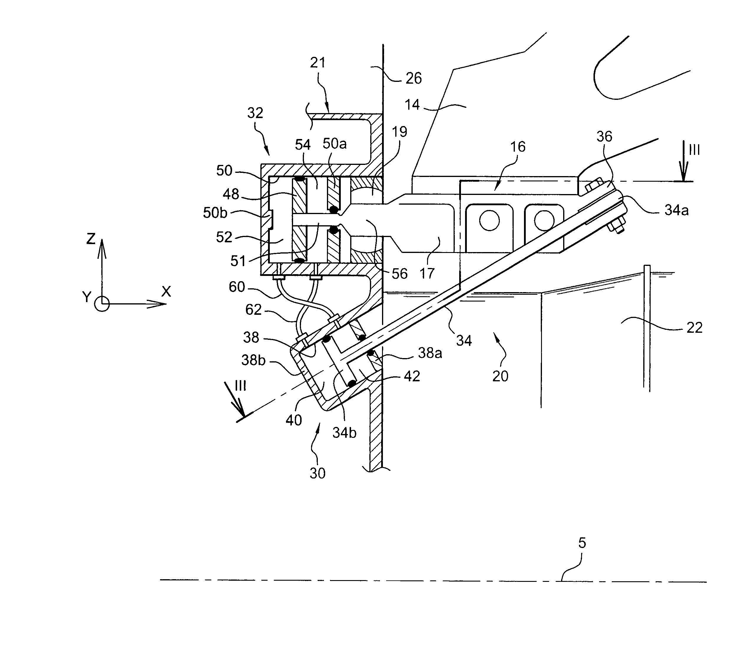
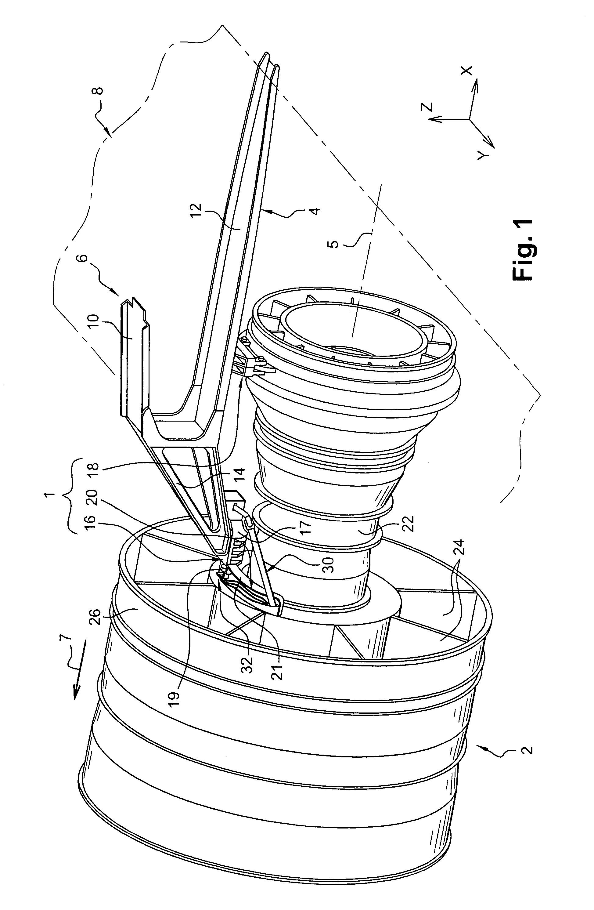
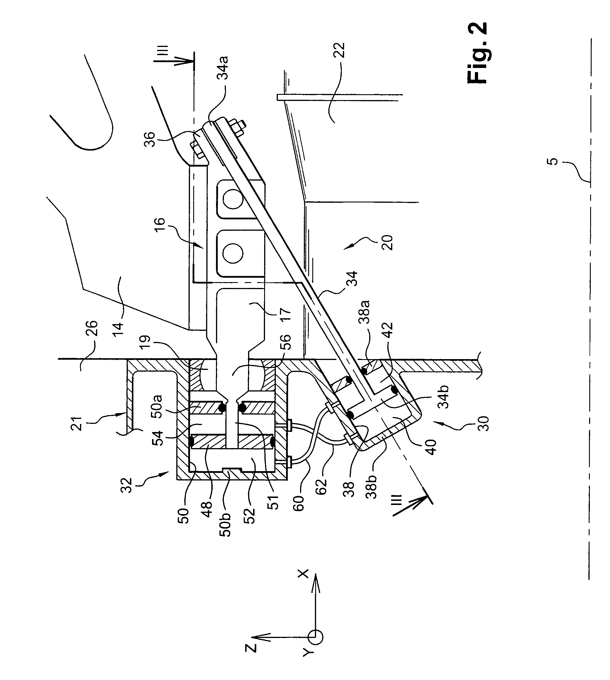
[0037]FIG. 1 shows a mounting system 1 according to a first preferred embodiment of this invention, this mounting system 1 being inserted between an aircraft engine 2 and a rigid structure 4 of an attachment strut 6 fixed under an aircraft wing shown diagrammatically for obvious reasons of clarity, and denoted generally by the numeric reference 8. Note that the mounting system 1 shown on this single figure is adapted to cooperate with a turbojet 2, but obviously it could be a system designed to suspend any other type of engine such as a turboprop, without departing from the scope of the invention.

[0038]Throughout the description given below, by convention, X is the direction parallel to a longitudinal axis 5 of the engine 2, Y is the direction oriented in the transverse direction of the aircraft, and Z is the vertical direction, these three directions being orthogonal to each other.

[0039]Secondly, the terms > and > should be considered with respect to a direction of movement of the ...


PUM


Abstract

This invention relates to a mounting system (1) inserted between an aircraft engine and a rigid structure of an attachment strut, the system particularly comprising a thrust resistance device (20). The thrust resistance device (20) comprises two lateral actuators (30) each provided with a rod (34) in which a forward end (34b) is a piston located inside a chamber (38) of a central casing (22) of the engine, the chamber (38) comprising a forward compartment (40) and an aft compartment (42). Moreover, the thrust resistance device (20) comprises a device (32) including a piston (48) fixed to the forward mount (16) and located inside a chamber (50) fixed to the central casing, the chamber (50) comprising a forward compartment (52) and an aft compartment (54), the forward compartment (52) of the chamber (50) being hydraulically connected to the aft compartments (42) of the actuators (30).

Description

TECHNICAL FIELD[0001]This invention relates in general to a mounting system inserted between an aircraft engine and a rigid structure of an attachment strut fixed under a wing of this aircraft.[0002]The invention also relates to an attachment strut for an aircraft engine fitted with such a mounting system, and this mounting system and the attachment strut can also be used on any type of aircraft.STATE OF PRIOR ART[0003]An aircraft attachment strut is designed to form the connecting interface between an engine and a wing of the aircraft. It transmits forces generated by the associated engine to the structure of this aircraft, and it also enables routing of the fuel, electricity, hydraulics and air between the engine and the aircraft.[0004]In order to transmit forces, the strut comprises a rigid structure, for example of the <<caisson>> type, in other words formed by the assembly of upper and lower stringers connected to each other through transverse ribs.[0005]Furthermore...

Claims


Application Information

Patent Timeline
Patent Type & Authority Patents(United States)
IPC IPC(8): B64D27/00B64D27/26
CPCB64D27/26B64D2027/268B64D2027/264
Inventor MARCHE, HERVE
Owner AIRBUS OPERATIONS (SAS)
Why Eureka
Try Eureka