Active pulse monitoring in a chemical reactor

a technology of active pulse and chemical reactor, which is applied in the field of chemical processes, can solve the problems of difficult to determine how much solid or liquid precursor is left in the container, the cycle can be more complex, and the precursor may be highly flammable, explosive, corrosive and/or toxic,

Inactive Publication Date: 2006-06-20
ASM INTERNATIONAL
View PDF6 Cites 22 Cited by
  • Summary
  • Abstract
  • Description
  • Claims
  • Application Information

AI Technical Summary

Problems solved by technology

Cycles can also be more complex.
One problem associated with such ALD reactors and other chemical processes that use solid or liquid precursors is that it is difficult to determine how much solid or liquid precursor is left in the container.
For example, low pressure is often required to volatilize the solid or liquid and the precursor may be highly flammable, explosive, corrosive and / or toxic.
Conventional measuring devices positioned in the container can be damaged and / or are impractical.
Operating in this manner is generally undesirable because it allows the concentration of the precursor in the reactor to drop below an ideal concentration range when the source is about to become depleted.
This can result in unused precursor remaining in the container, such that refilling is performed prematurely and the reactor downtime is increased (i.e., the duration of reactor use between refilling is reduced).
For example, it requires that the outlet of the container be closed, which increases the downtime of the reactor.
This can result in contamination and CVD-type reactions between the precursors, thereby compromising the ALD process.

Method used


Image

  • Active pulse monitoring in a chemical reactor
  • Active pulse monitoring in a chemical reactor
  • Active pulse monitoring in a chemical reactor

Examples


first embodiment

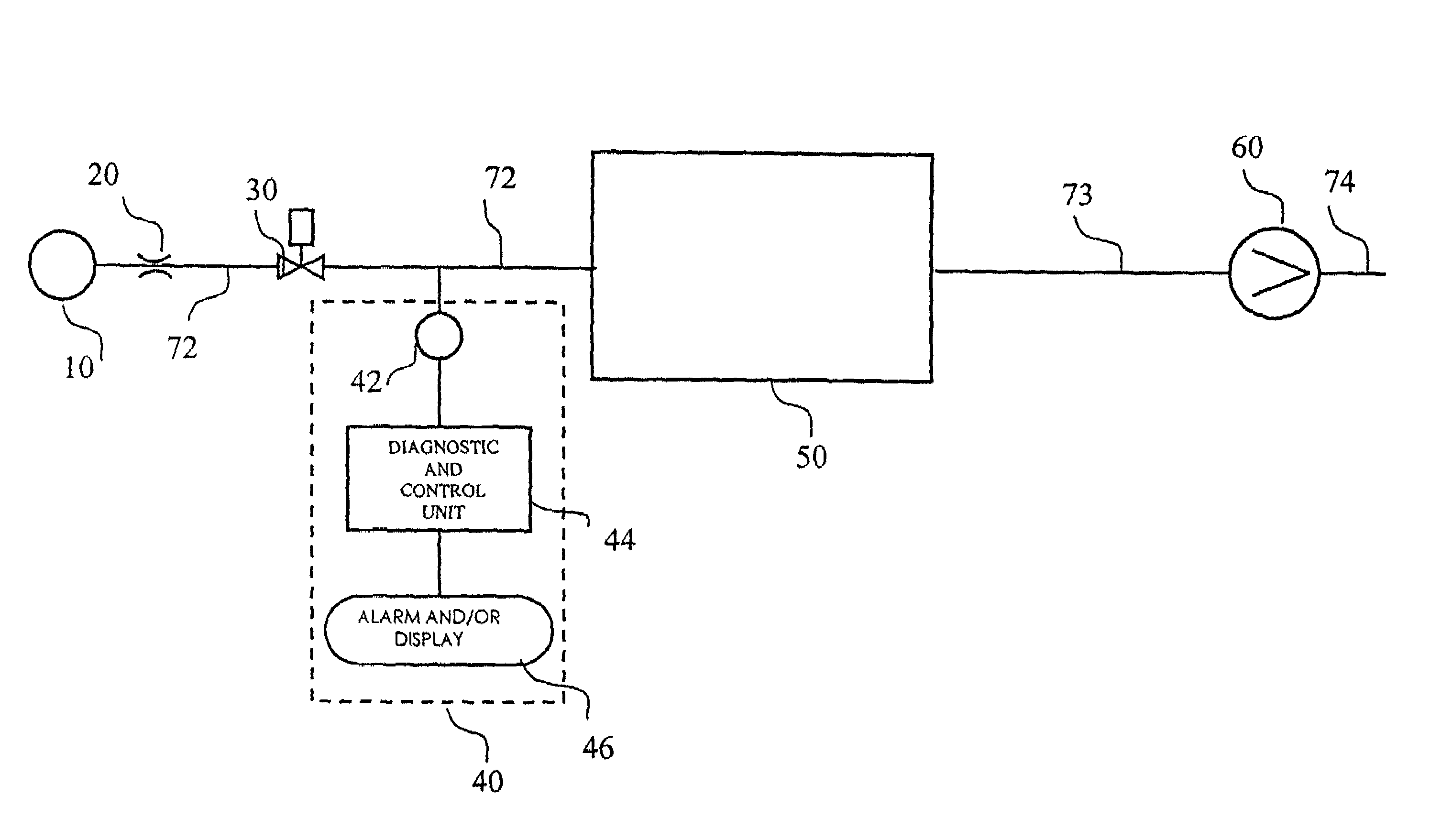
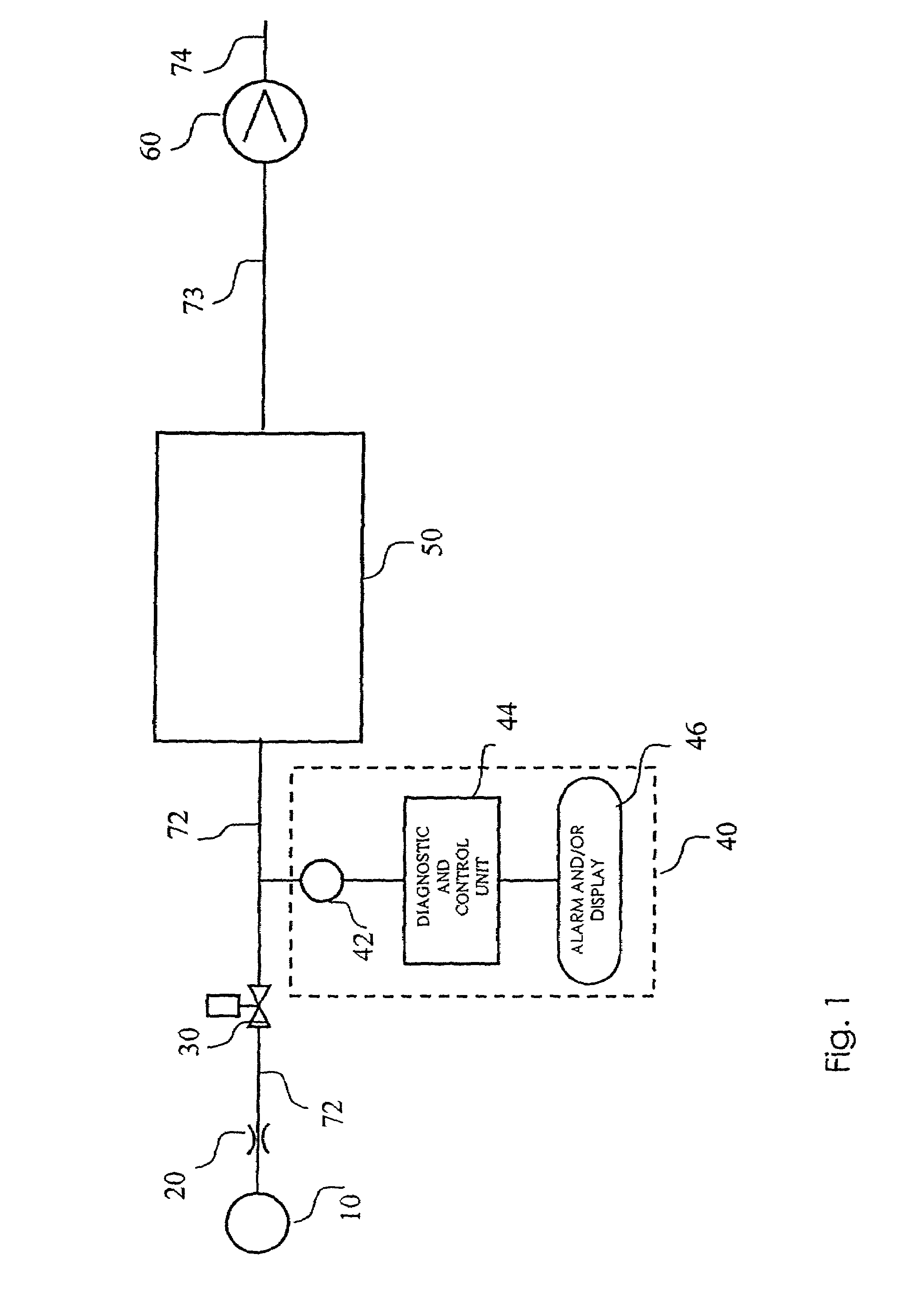
[0027]FIG. 1 is a schematic illustration of an apparatus for supplying repeated vapor phase reactant pulses to a reaction chamber according to the present invention. The system as shown in FIG. 1 comprises a reactant source 10, connected through a reactant conduit 72 to a reaction chamber 50. The reactant can be present in the reactant source 10 as a compressed gas or as a vapor phase reactant in communication with a part of the reactant that is present in liquid or solid phase, provided that the vapor pressure of the reactant is sufficiently high to transport the reactant to the reaction chamber. Gases are removed from the reaction chamber 50 by a vacuum pump 60 via an outlet conduit 73 and exhausted through a pump exhaust 74. A reactant valve 30 is placed in the reactant conduit 72 to induce pulse-wise supply of the reactant to the reaction chamber 50 through repeated switching of the reactant valve 30. By repeated and reproducible switching of the reactant valve 30 a number of su...

second embodiment

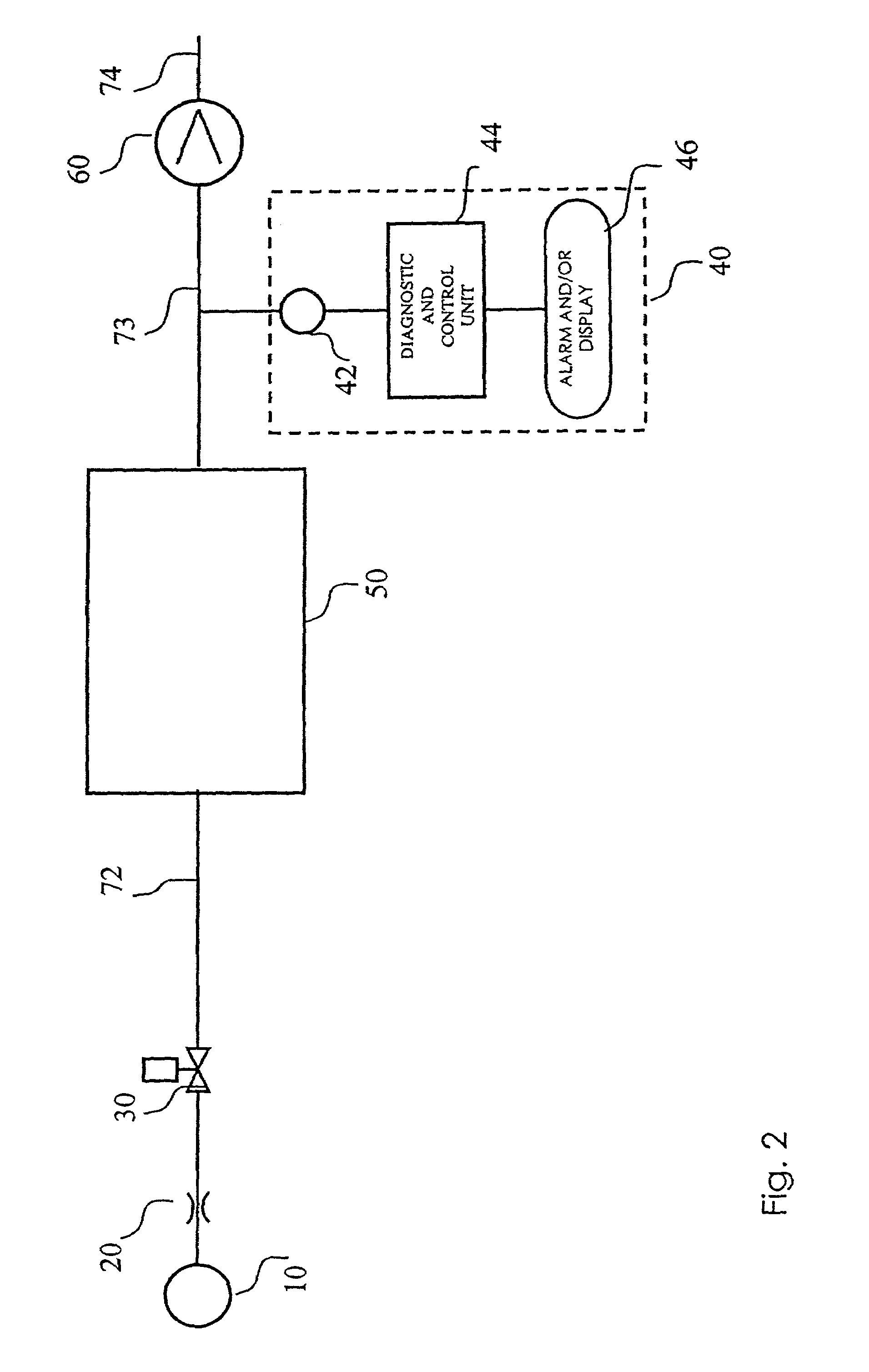
[0034]FIG. 2 shows the present invention wherein similar components are indicated with like reference numbers as in FIG. 1. In FIG. 2, the sensor 42 is positioned in communication with the outlet conduit 73, which connects the reaction chamber 50 with the vacuum pump 60.

third embodiment

[0035]FIG. 3 shows the present invention wherein similar components are indicated with like reference numbers as in FIG. 1. In the reactant conduit 72, which connects the reactant source 10 with the reaction chamber 50, a mass flow controller 80 is installed to create a substantially constant flow of reactant. A bypass conduit 94 is connected at one end to the reactant conduit 72 and at the other end to an exhaust (not shown). A bypass valve 34 is connected with the reactant valve 30, through a connection 33 such that the valves 30 and 34 are oppositely switched simultaneously. Consequently, when the reactant valve 30 is opened, the bypass valve 34 is closed, and when reactant valve 30 is closed, the bypass valve 34 is opened. The connection 33 can be operated mechanically, pneumatically or via a control loop.

[0036]The invention will now be illustrated by two further examples, which relate to liquid or solid reactant sources and employing a carrier gas to transport the reactant from...


PUM

PropertyMeasurementUnit
pressureaaaaaaaaaa
temperatureaaaaaaaaaa
time resolutionaaaaaaaaaa

Abstract

A method and apparatus for determining changes in a supply system, designed to supply repeated pulses of a vapor phase reactant to a reaction chamber is disclosed. One embodiment involves providing the reactant source, and a gas conduit to connect the reactant source to the reaction chamber, a valve positioned in communication with the reactant source such that switching of the valve induces vapor phase reactant pulses from the reactant source to the reaction chamber and a sensor positioned in communication with the reactant source and configured to provide a signal indicative of a characteristic parameter of the reactant pulse as a function of time. A curve is derived from the signal and the shape of the curve is monitored to determine changes in the curve shape over time during subsequent pulses.

Description

BACKGROUND OF THE INVENTION[0001]1. Field of the Invention[0002]The present invention relates to chemical processes in which a processing chemical is supplied in the form of repeated pulses of a gas phase or vapor phase reactant. More particularly, the invention relates to chemical processes for producing a thin film on a substrate by subjecting the substrate to repeated pulses of gas or vapor-phase reactants.[0003]2. Description of the Related Art[0004]There are several vapor deposition methods for growing thin films on the surface of substrates. These methods include vacuum evaporation deposition, Molecular Beam Epitaxy (MBE), different variants of Chemical Vapor Deposition (CVD) (including low-pressure and organometallic CVD and plasma-enhanced CVD), and Atomic Layer Epitaxy (ALE), which is more recently referred to as Atomic Layer Deposition (ALD).[0005]ALE or ALD is a deposition method that is based on the sequential introduction of precursor species (e.g., a first precursor an...

Claims


Application Information

Patent Timeline
Patent Type & Authority Patents(United States)
IPC IPC(8): G01N33/00C23C16/455G01N1/28C23C16/44C23C16/52C30B25/14C30B25/16G01F1/72H01L21/205
CPCC23C16/4402C23C16/45525G01F1/72C30B25/165C30B25/14Y10T436/12
Inventor BONDESTRAM, NIKLASHENDRIKS, MENSO
Owner ASM INTERNATIONAL
Why Eureka
Try Eureka