Phase angle control for synchronous machine control

a synchronous machine and phase angle technology, applied in electrical control, hybrid vehicles, electronic commutators, etc., can solve the problems of preventing the possibility of simple control of field strength, requiring a long time, and requiring high production costs

Inactive Publication Date: 2006-06-20
J L BEHMER CORP
View PDF24 Cites 51 Cited by
  • Summary
  • Abstract
  • Description
  • Claims
  • Application Information

AI Technical Summary

Problems solved by technology

However, PM type machines are generally expensive to produce and preclude the possibility of simple control of field strength needed when the synchronous machine under a varying RPM is to be both a motor and generator and under total control in either mode.
Further, permanent-magnets are not permanent when inadvertently subjected to extreme high currents and extreme high temperature.
These types of hybrid-synchronous machines provide adequate improvements in control, however, they lack quick response and have difficulty in handling large KW needed for hybrid automobiles.
They also lack a simple method of voltage control while in generating mode for braking.
However, the relatively high costs of magnets, operating temperature limitations (100–150° C.) and the danger of PM demagnetization at high transient torques or at short circuit restrict the applications of such PM motors.
Vector control of induction motors provides almost equally fast speed dynamics with a lower cost rugged motor but with a slightly more complex and parameter-dependent controller and higher motor losses and static power converter ratings.
In applications where sustained large torque, low speed running is required, or in high precision machining (e.g., spindle) induction motor drives, the high rotor cage losses pose serious cooling and rotor thermal deformation problems, respectively.
These types of pseudo-synchronous motors (essentially stepping motors) are lacking for all of the reasons set forth above including high heat loss in large KW sizes for hybrid automobiles, poor torque control at zero to very low RPM, difficulty controlling position especially while reversing and difficulty in controlling voltage while generating.

Method used


Image

  • Phase angle control for synchronous machine control
  • Phase angle control for synchronous machine control
  • Phase angle control for synchronous machine control

Examples


Embodiment Construction

[0045]Certain terminology is used in the following description for convenience only and is not limiting. The words “right,” and “left,”“lower,” and “upper” designate directions in the drawings to which reference is made. The words “inwardly” and “outwardly” refer to directions toward and away from, respectively, the geometric center of the object discussed and designated parts thereof. The terminology includes the words above specifically mentioned, derivatives thereof and words of similar import. Additionally, the word “a” is used in the claims and in the corresponding portions of the Specification, means “at least one.”

I. General Description:

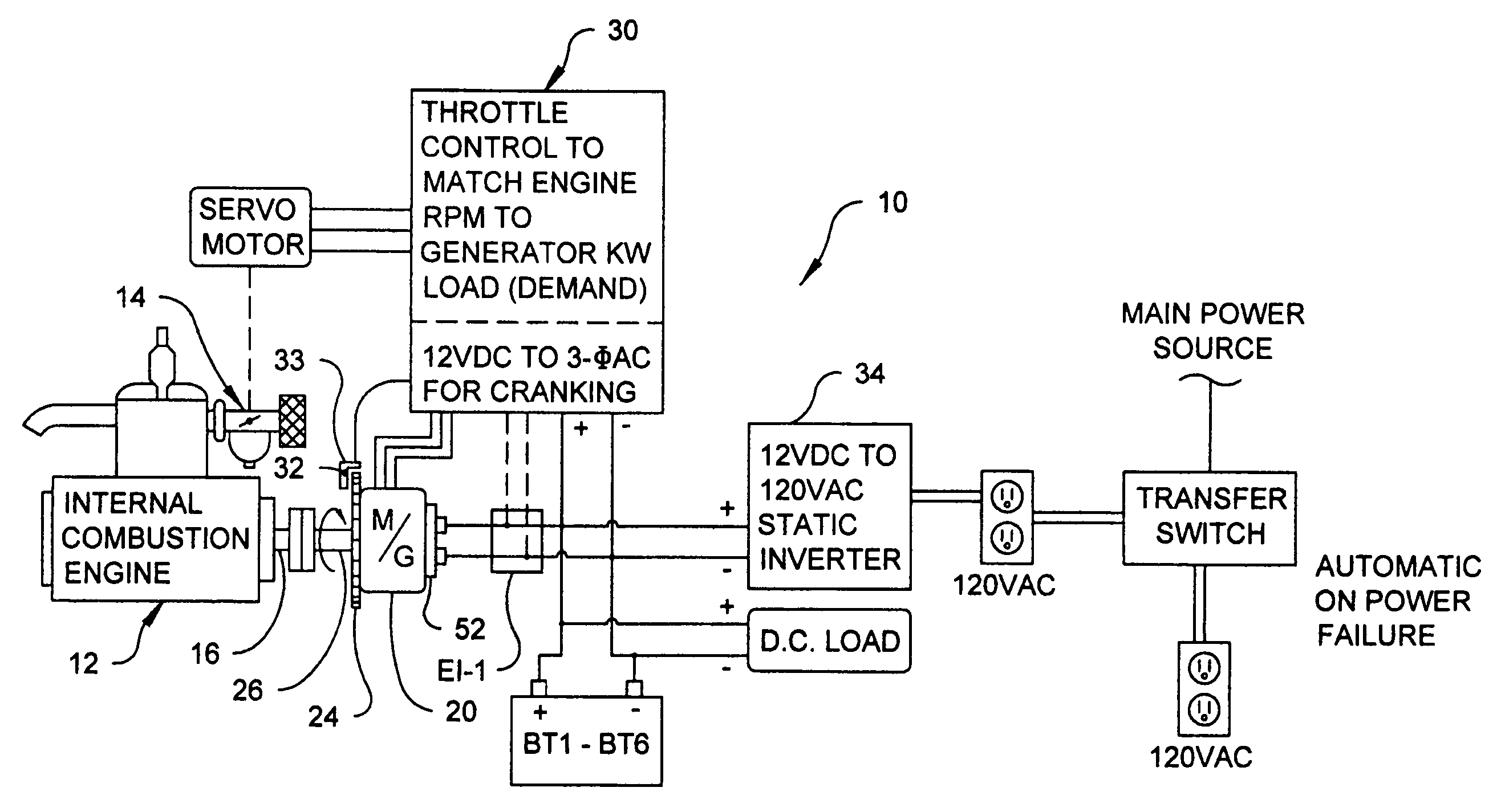
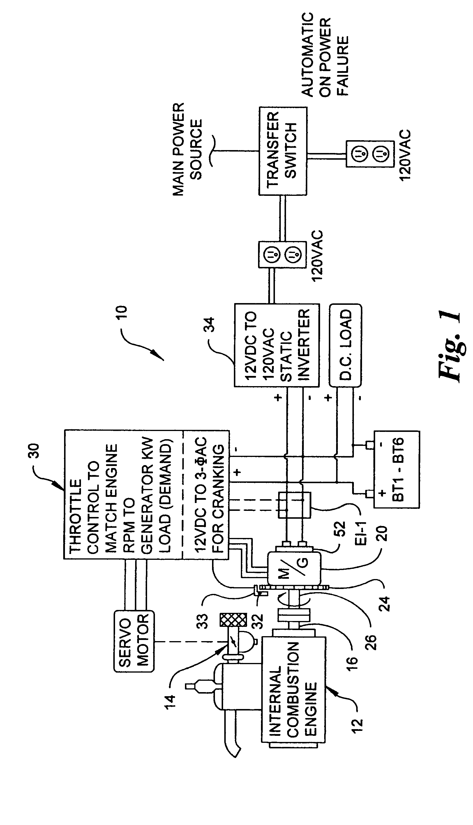
[0046]Referring to the drawings in detail, wherein like reference numerals indicate like elements throughout, there is shown in FIG. 1 a typical internal combustion engine powered generator set 10 which incorporates phase angle control in accordance with the present invention. The internal combustion powered generator set or gen-set 10 include...


PUM


Abstract

A synchronous machine with 3-phase sensors set 120° apart and 90° advanced is used to provide commutation from a direct current source. A time delay circuit with an electronically implemented algorithm controls torque by delaying the 90° advance. This delay is controlled by a linear voltage, independent of frequency, and can be used to control position, speed, or acceleration. A delay beyond 90° advance causes commutation to cease, and the alternating current machine switches to a generator, indicative of motive power being applied. If motive power ceases, the alternating current machine switches to a motor. Controlled switching can be less than half of one hertz.

Description

CROSS-REFERENCE TO RELATED APPLICATIONS[0001]This application claims the benefit of co-pending U.S. Provisional Patent Application No. 60 / 507,555, filed Oct. 1, 2003, entitled “Phase Angle Control for Synchronous Machine Control,” the disclosure of which is incorporated herein by reference.BACKGROUND OF THE INVENTION[0002]The present invention relates generally to an apparatus and method for controlling electrical motors and generators, and more particularly, to an improved apparatus and method for controlling a synchronous electrical machine which selectively acts as both a motor and a generator by controlling phase angle.[0003]A synchronous electrical motor can also act as a synchronous electrical generator, and therefore, devices which act as either a synchronous electrical motor or generator are referred to as synchronous electrical machines. Mechanical energy is changed into electrical energy by movement of a conductor through a magnetic field. The converse is also true wherein...

Claims


Application Information

Patent Timeline
Patent Type & Authority Patents(United States)
IPC IPC(8): H02P1/46F02D29/06F02D41/02F02D41/08F02D41/34H02PH02P9/04
CPCB60K6/26B60K6/52F02D29/06F02D41/009F02D41/0205F02D41/083H02P6/142H02P9/04H02P9/48B60K6/48H02P2101/45B60W2520/26B60W2520/28Y02T10/6221Y02T10/6265H02P2101/30H02P6/15Y02T10/62
Inventor FENLEY, THOMAS D.
Owner J L BEHMER CORP
Why Eureka
Try Eureka