Supercharging system for gas turbines

a gas turbine and supercharging technology, applied in the direction of efficient propulsion technologies, machines/engines, mechanical apparatuses, etc., can solve the problems of limited use of new turbines, inability to allow the turbines to run at their full design capacity, and special troublesome characteristics, so as to increase the turbine capacity and reduce the installed cost of the system

Inactive Publication Date: 2006-06-27
ENHANCED TURBINE OUTPUT HLDG
View PDF11 Cites 236 Cited by
  • Summary
  • Abstract
  • Description
  • Claims
  • Application Information

AI Technical Summary

Benefits of technology

[0015]One of the principal objectives and advantages of the invention is the ability to increase turbine capacity under summer-peaking conditions while reducing the installed cost of the system based on capacity at summer-peaking conditions. Related objectives of the invention are to create a relatively compact system that is not excessively comp...

Problems solved by technology

This characteristic is especially troublesome for gas turbines used in electrical power generation since the peak electricity demand usually coincides with the highest ambient air temperatures.
Larger reductions are possible in warm, dry climates such as those of the southwestern U.S. While direct evaporative cooling is helpful, it does not allow the turbines to run at their full design capacity.
This approach could give large theoretical advantages, but it required special sizing of the generator which limited its use to new turbines.
In addition, the systems used a single fan with inlet vanes for control purposes, which reduced the efficiency of the system.
This paper shows that while evaporative cooling is extremely attractive, the economics of supercharging are not very attractive, with payback periods of over 10 years for simple cycles.
Supercharging is more attractive in combined-cycle plants, but its economics are still marginal.
The supercharging systems described in this paper are virtually identical to those from the 1960s, so supercharging has not advanced significantly despite decades of turbine development.
One significant problem in the prior art is that the supercharging arrangements r...

Method used


Image

  • Supercharging system for gas turbines
  • Supercharging system for gas turbines
  • Supercharging system for gas turbines

Examples


Embodiment Construction

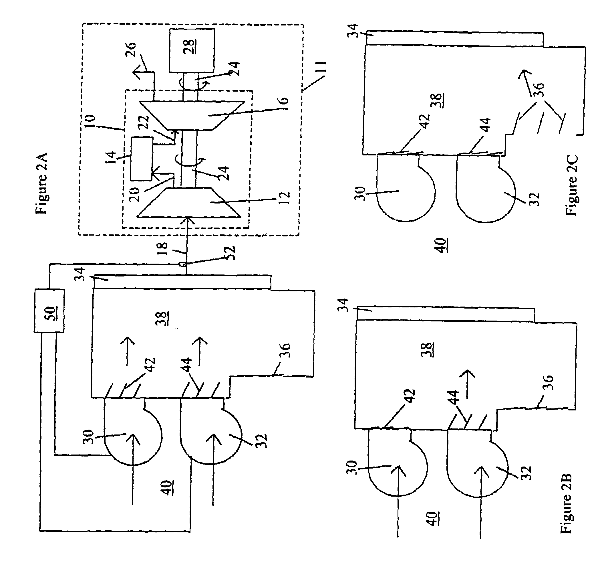
[0034]FIG. 2A shows a preferred embodiment of the invention. A gas turbine power plant 11 contains a gas turbine system 10 and a generator 28. Gas turbine system 10 includes a compressor 12, a burner 14, and a turbine 16. The turbine 16 shares a common shaft 24 with the compressor 12 and the generator 28. The compressor 12 receives compressor inlet air stream 18 and pumps it to a higher pressure to create pressurized 5 burner inlet air stream 20 which is supplied to burner 14. Burner 14 heats the air from stream 20 and supplies the resulting heated turbine inlet air stream 22 to the turbine 16. Turbine 16 rotates in response to the received heated inlet air stream 22, thereby rotating shaft 24 which in turn rotates generator 28 to generate electric power. Exhaust air stream 26 exits the turbine 16. This exhaust stream 26 may go directly into the atmosphere, or it can enter a steam boiler in the case of a combined cycle plant as described below in connection with FIG. 13.

[0035]While ...


PUM


Abstract

A supercharging system for gas turbine power plants (11). The system includes a supercharging fan (30, 32) and controller (50) for limiting turbine power output to prevent overload of the generator (28) at lower ambient temperatures. The controller can limit power output by burner control, inlet temperature control, control of supercharging fan pressure and other options. The system can be retrofit on an existing turbine without replacing the generator and associated parts.

Description

[0001]Applicant claims the benefit of co-pending U.S. provisional patent application Ser. No. 60 / 138,848 filed Jun. 10, 1999; Ser. No. 60 / 139,894 filed Jun. 22, 1999; Ser. No. 60 / 152,277 filed Sep. 3, 1999; Ser. No. 60 / 159,207 filed Oct. 13, 1999; and Ser. No. 60 / 195,302 filed Apr. 10, 2000. This application is a continuation-in-part of co-pending patent application Ser. No. 09 / 388,927, filed Sep. 2, 1999 now U.S. Pat. No. 6,308,512.BACKGROUND OF THE INVENTION[0002]1. Field of the Invention[0003]This invention relates generally to gas turbine power generation systems and more particularly relates to a supercharging system for improving the capacity of gas turbine power plants at high ambient temperatures. Specifically, the system uses a supercharging fan combined with a controller to pressurize inlet air to the turbine to allow operation with existing turbines; the supercharging fan is preferably combined with an inlet air cooling system.[0004]2. Background and Prior Art[0005]It has...

Claims


Application Information

Patent Timeline
IPC IPC(8): F02G3/00F02C1/00
CPCF02C7/057F02C7/1435Y02T50/675Y02T50/60
Inventor KOPKO, WILLIAM L.
Owner ENHANCED TURBINE OUTPUT HLDG
Why Eureka
Try Eureka