
Method and apparatus for excavating earth to a desired depth

a technology for excavating earth and basements, applied in mechanical machines/dredgers, distance measurement, instruments, etc., can solve problems such as increased miscommunication, difficulty in identifying the depth of the earth, and difficulty in conventional surveying techniques described above, so as to reduce the possibility of miscommunication, eliminate the risk of harm, and reduce the cost of excavation

Inactive Publication Date: 2006-06-27
WILCOX ALAN R
View PDF31 Cites 6 Cited by
  • Summary
  • Abstract
  • Description
  • Claims
  • Application Information

AI Technical Summary

Benefits of technology

[0009]One advantage of the invention provides a method for excavating a below grade opening that reduces the cost of excavation.
[0010]Another advantage of the invention provides a reduced possibility for miscommunication and error in obtaining elevation measurements while excavating the opening.
[0011]Another advantage of the invention provides a method and apparatus for excavating a parcel of land that eliminates the risk of harm to a rod man.
[0012]Another advantage of the invention provides an economical and efficient method and apparatus to excavate a parcel of land.
[0013]Another advantage of the invention provides an excavation system that is of relatively simple design and manufacture.

Problems solved by technology

The conventional surveying techniques described above can be slow and tedious, since a rod man is needed to move the grade stick to various locations.
In addition, the rod man can be subjected to difficulties, such as pests, weeds, brush, and ultimately dangerous situations that may result from depths at the excavation site presenting a risk of cave in.
Additionally, the requirement for a rod man increases the possibility for miscommunication between the surveyor and the rod man and the need for two people to accomplish excavation adds inherent costs in the excavation process.

Method used


Image

  • Method and apparatus for excavating earth to a desired depth
  • Method and apparatus for excavating earth to a desired depth
  • Method and apparatus for excavating earth to a desired depth

Examples


Embodiment Construction

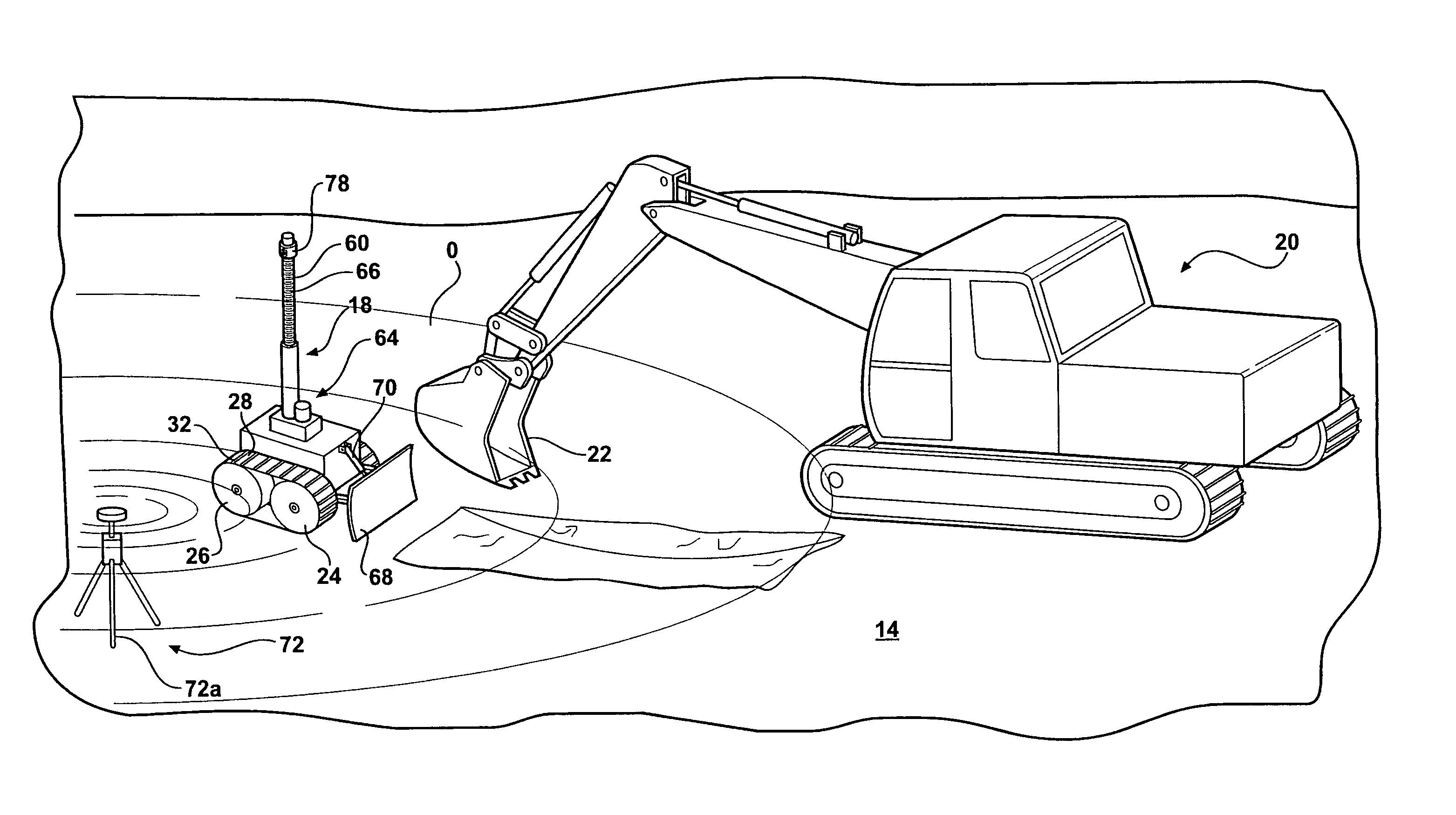
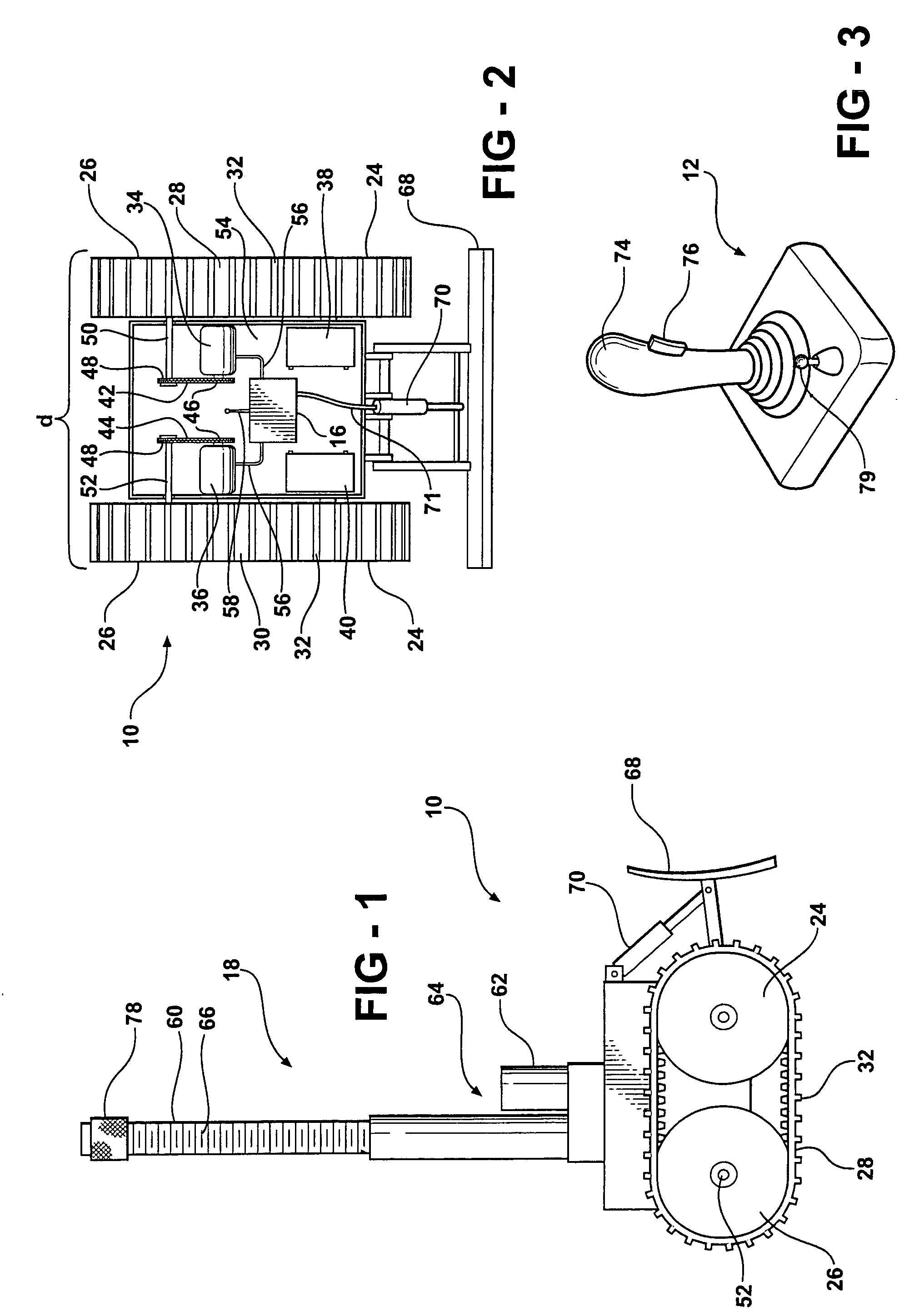
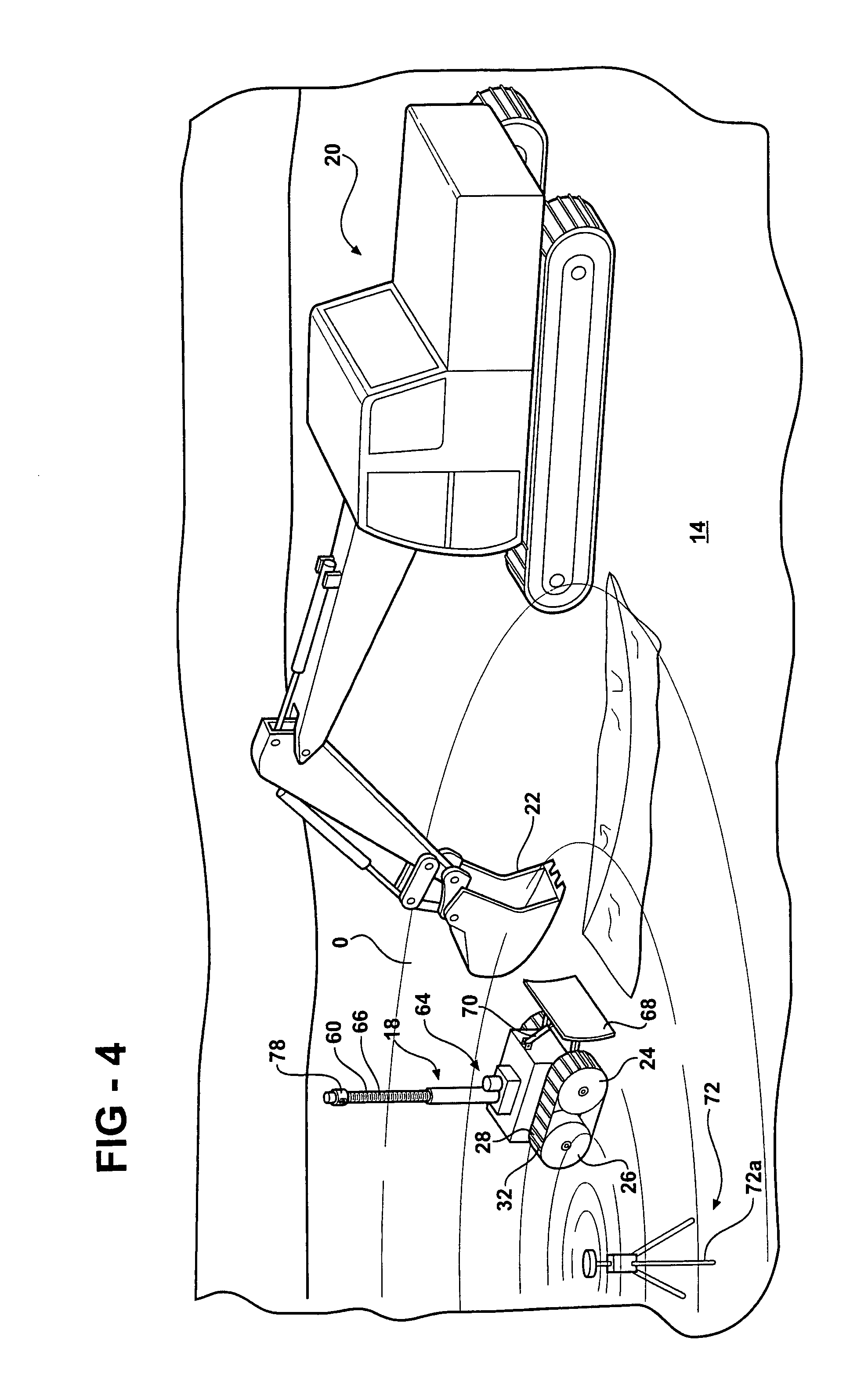
[0020]Referring in more detail to the drawings, FIGS. 1 and 2 illustrate one presently preferred embodiment of a elevation measurement vehicle, referred to as a first vehicle 10 for facilitating excavating a basement or other opening O in a parcel of land 14 (FIG. 4). The first vehicle 10 is arranged for remote control operation so that a remote control transmitter 12 (FIG. 3) can send a signal to a first receiver 16 on the first vehicle 10 for maneuvering the first vehicle 10 within the opening O being excavated. The first receiver 16 is a radio frequency or other such commercial device having a microprocessor 17 either integrally formed therewith or separate therefrom and is typically obtainable from a laser equipment retailer. Once the first vehicle 10 is in the desired floor area of the opening O, an elevation measurement may be obtained from a vertically disposed graduated measurement device 18 on the first vehicle 10. Once the elevation measurement is obtained, the first vehic...


PUM


Abstract

A system and method of facilitating excavating a below grade opening at a construction site in a parcel of land includes a first vehicle having a motor operably connected to at least a pair of traction members and a second excavating vehicle. The motor is operably connected to a first receiver for receiving a signal from a remotely controlled transmitter to actuate the motor. Upon actuation of the motor, the motor rotates the traction members for maneuvering the first vehicle within the opening. The first vehicle has a graduated measurement device mounted generally vertically thereon for remotely controlled vertical telescopic movement. A second beam receiver is mounted to the graduated measurement device for receiving a laser beam from a laser transmitter to facilitate precise determination of the depth of the floor of the opening.

Description

BACKGROUND OF THE INVENTION[0001]1. Field of the Invention[0002]The invention relates generally to a method and apparatus for excavating a basement or like below grade opening.[0003]2. Related Art[0004]At a construction site, a basement is typically constructed by excavating a portion of a parcel of land. Typically, the excavation must be continually monitored to determine how much more earth needs to be excavated. In a conventional process, an elevation survey is performed utilizing a transit and a target. Commonly, the transit is a laser transmitter used on the ground area surrounding the opening and the target is a laser receiver attached to a grade stick. The grade stick, and thus the laser receiver, is placed into the opening area and as the excavation proceeds, the elevation differential between the target and bottom of the excavation is determined. With this information, the necessary additional excavation can be performed to achieve the desired elevation for the floor of the...

Claims


Application Information

Patent Timeline
Patent Type & Authority Patents(United States)
IPC IPC(8): G01C3/00A01B79/00
CPCG01C5/00Y10S37/907
Inventor WILCOX, ALAN R.
Owner WILCOX ALAN R
Learn More