Apparatus for converting side-to-side driving motion to rotational motion with a spring assembly and system for tuning the spring assembly

a technology of rotating motion and spring assembly, which is applied in the direction of cleaning machines, carpet cleaners, cleaning machines, etc., can solve the problems of unreliable, noisy, unreliable, and unacceptably low torsion spring rate, and achieve the effect of less resistance to twisting action

Inactive Publication Date: 2006-06-27
KONINKLIJKE PHILIPS ELECTRONICS NV
View PDF10 Cites 103 Cited by
  • Summary
  • Abstract
  • Description
  • Claims
  • Application Information

AI Technical Summary

Benefits of technology

[0006]Accordingly, one aspect of the present invention is an apparatus and corresponding method of converting side-to-side drive motion to rotational motion for a workpiece portion of an appliance, comprising: a movable base mounting element, capable of being driven in a translational reciprocal motion; a fixed position mounting element spaced apart from the base element, the fixed mounting element being held so that it does not move during operation of the apparatus; a spring member connected to the base element and to the fixed mounting element; and a drive shaft member connected to the base element and rotatable relative to the fixed mounting element, the drive shaft having a workpiece mounted thereto, wherein the spring member is so configured and arranged that it is substantially less resistant to twisting action than to bending action, the twisting action producing workpiece rotation at a preselected frequency.

Problems solved by technology

However, such linkage arrangements frequently have undesirable backlash action, which can cause damping, vibration and noise.
Torsion springs can be used, but they are usually made from coil-type springs, which typically do not combine the required radial stiffness with an acceptably low torsion spring rate.
Most of these known devices require various bearing structures, which are often complex, noisy and unreliable.
Bearings also have their own backlash conditions.

Method used


Image

  • Apparatus for converting side-to-side driving motion to rotational motion with a spring assembly and system for tuning the spring assembly
  • Apparatus for converting side-to-side driving motion to rotational motion with a spring assembly and system for tuning the spring assembly
  • Apparatus for converting side-to-side driving motion to rotational motion with a spring assembly and system for tuning the spring assembly

Examples


Embodiment Construction

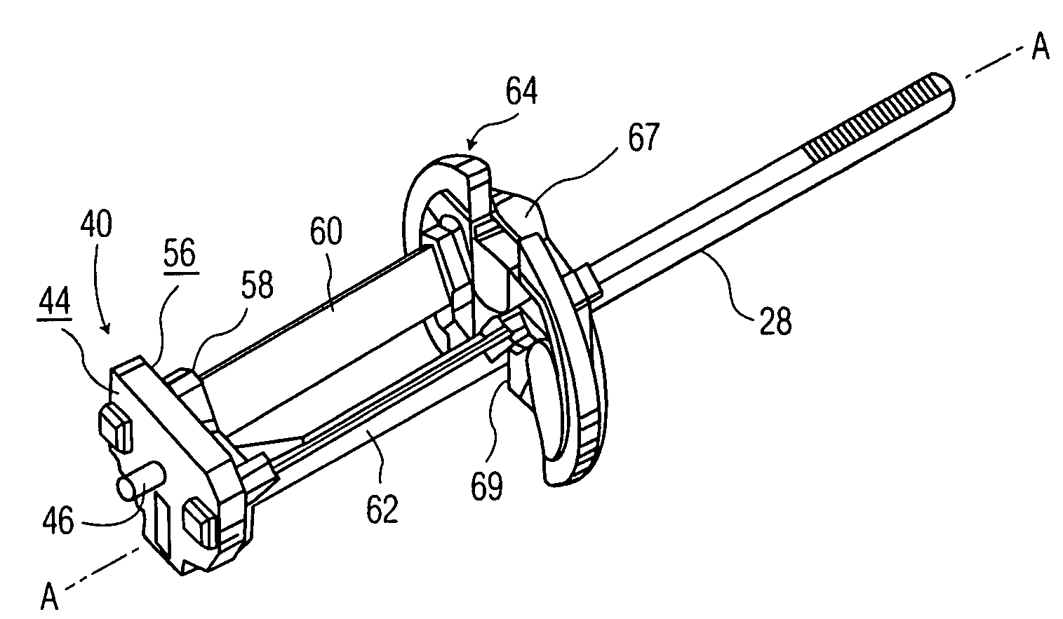
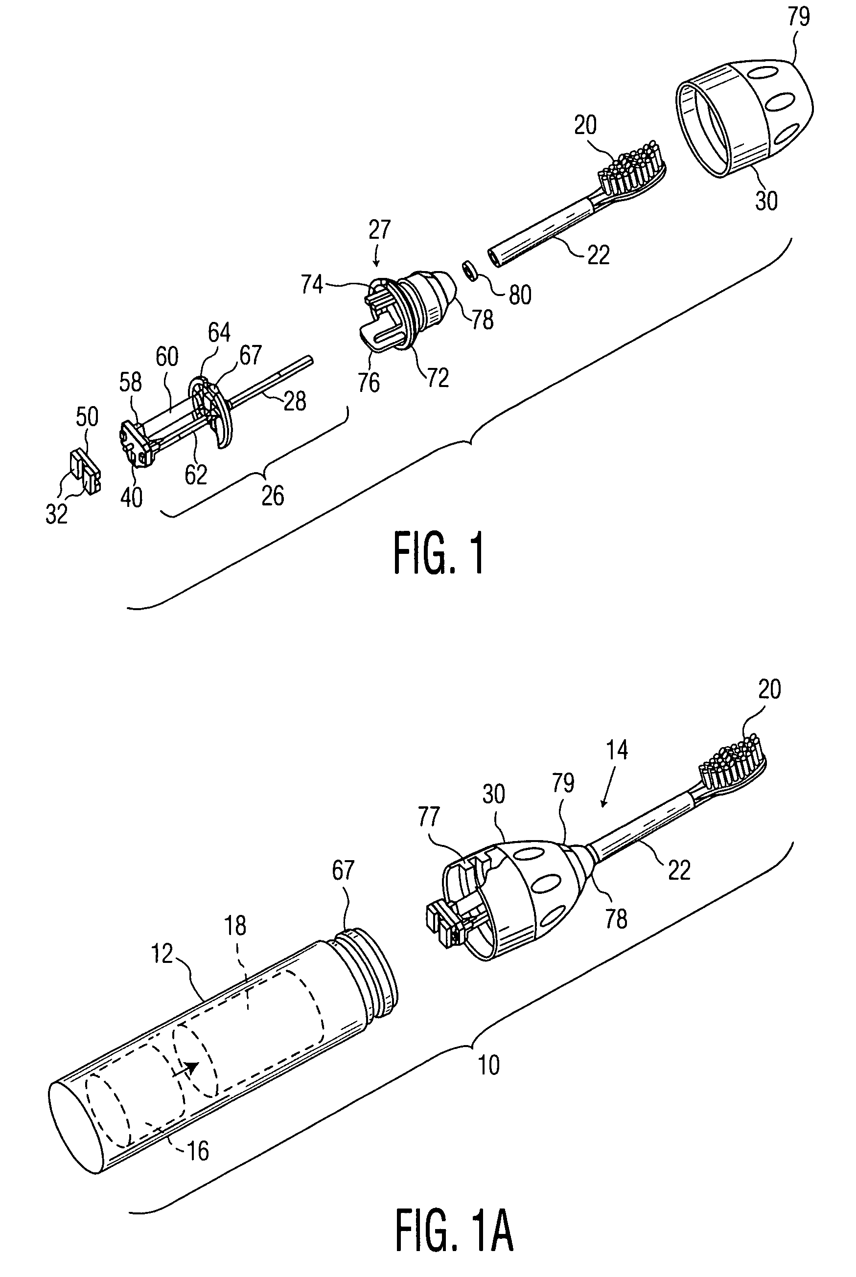
[0016]FIGS. 1 and 1A show a power toothbrush 10 which includes a handle portion 12 and a head portion 14. The handle portion includes a power source, such as a rechargeable battery 16, and a drive assembly, shown generally at 18. The head portion 14 includes a workpiece element, e.g. a brushhead 20, which comprises a plurality of bristles arranged in a selected pattern, a brushhead arm 22 on which brushhead 10 is mounted, a motion conversion assembly, shown generally at 26, and a mounting assembly 27 for the motion conversion assembly.

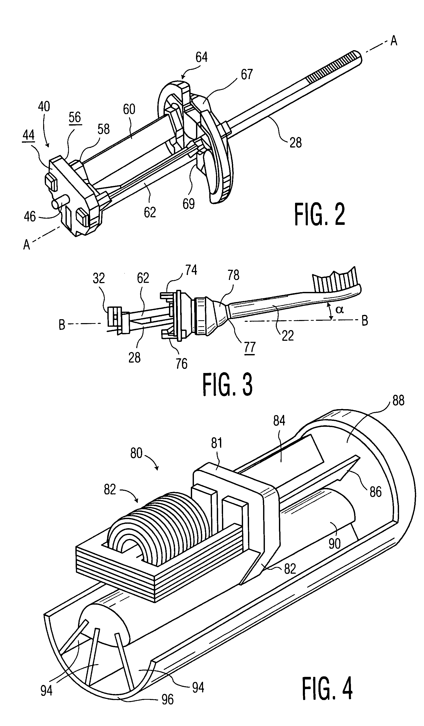
[0017]The motion conversion assembly 26 in the embodiment shown converts a linear action to rotation of a drive shaft 28 which extends into and joins with brushhead arm 22 for rotation thereof and rotation of brushhead 20. Head portion 14 also includes a nut element 30, which connects head portion 14 to handle portion 12 and to which the mounting assembly 27 is fixedly secured.

[0018]In the appliance shown, the driving assembly 18 is an electromagnet, w...


PUM

PropertyMeasurementUnit
angleaaaaaaaaaa
angleaaaaaaaaaa
angleaaaaaaaaaa

Abstract

The apparatus for converting side-to-side to rotational motion for a workpiece includes a spring assembly with a movable base mounting element which is driven in a slightly arcuate reciprocal side-to-side motion and a fixed mounting element spaced apart from the base element and mounted in the appliance so that it does not rotate or move in operation of the apparatus. A spring member, such as two planar leaf springs positioned at an angle to each other, is mounted between the movable base element and the fixed mounting element. A drive shaft member extends from the movable base element through the fixed mounting element and beyond. A workpiece such as a brushhead is mounted on the distal end of the drive shaft. The spring member is configured so that it is substantially less resistant to twisting action than bending action, such that the side-to-side motion of the base element results in rotation of the workpiece.A method for tuning resonant spring assembly systems used in appliances such as power toothbrushes, particularly leaf spring systems, includes the step of measuring the frequency-dependent amplitude of the appliance workpiece, and then removing a portion of the spring member so as to decrease its spring rate sufficiently that the resonant frequency of the spring member closely approximates the drive frequency of the appliance.

Description

TECHNICAL FIELD[0001]This invention relates generally to small appliances, such as, for instance, toothbrushes, and more specifically concerns a spring structure for converting a side-to-side driving action into a rotary workpiece action. The invention also concerns a method for tuning the spring structure to a selected natural resonant frequency or amplitude during manufacture.BACKGROUND OF THE INVENTION[0002]Small appliances have various workpiece motions. In some cases, the drive motion is the same as the workpiece motion; in other cases, it is desirable to convert a particular drive motion into a different workpiece motion, such as a side-to-side drive motion to a rotary motion. The magnetic driver shown in U.S. Pat. No. 5,189,751 moves one end of an elongated pivoted arm to which is attached a toothbrush element, in a side-to-side (back and forth), slightly arcuate manner. The workpiece vibrates in a particular manner accordingly. While that workpiece motion does provide good r...

Claims


Application Information

Patent Timeline
Patent Type & Authority Patents(United States)
IPC IPC(8): H02K7/14A46B13/00A61C17/22A61C17/00A61C17/34B26B19/28F16F1/18F16H21/44F16H25/18H02K33/00
CPCA61C17/3418A61C17/3481B26B19/282Y10T29/49718F16H25/18A61C17/34
Inventor GREZ, JOSEPH W.GUEBLE, JEFFREY R.WOOD, JERRY C.NELSON, DEVIN M.MILLER, KEVIN A.HANELA, CRAIG D.TABER, BRUCE E.TAYLOR, RICHARD K.BRYANT, WILLIAMHALL, SCOTT E.LOIBNEGGER, ANDREASVAN RENS, PIET C. J.SADEK, KURTBARTEN, PAULUS L. W. M.LEITNER, D. I. STEPHAN
Owner KONINKLIJKE PHILIPS ELECTRONICS NV
Why Eureka
Try Eureka