
Arrangement for the optical detection of a moving target flow for a pulsed energy beam pumped radiation

a technology of pulsed energy beam and moving target flow, which is applied in the direction of optical radiation measurement, instruments, spectrophotometry/monochromators, etc., can solve the problems of not providing information about wavelength stability and energy stability of radiation, and affecting the quality of radiation

Active Publication Date: 2006-06-27
USHIO DENKI KK
View PDF6 Cites 45 Cited by
  • Summary
  • Abstract
  • Description
  • Claims
  • Application Information

AI Technical Summary

Benefits of technology

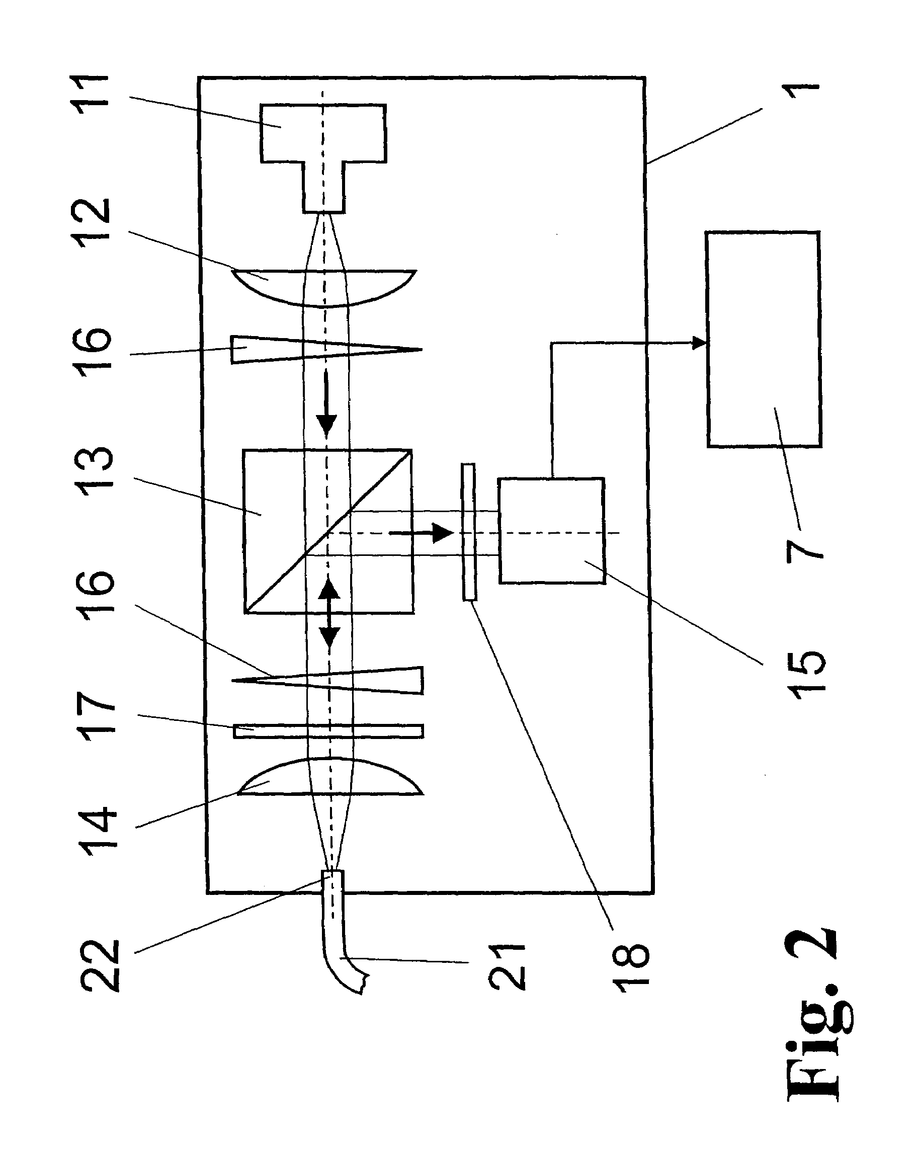
The invention is about a new way to detect and synchronize the movement of a target with a pulsed energy beam for plasma generation. The target is a moving material that generates plasma for radiation emission. The invention solves the problem of the target being exposed to the plasma and resulting in damage and interference with the detection process. The invention uses an optical detection system with a sensor unit and a projection module to observe the target flow and receive the reflected light. The sensor unit contains optical elements for generating the transmission light, coupling it into a light waveguide, and coupling it out. The detection module is located close to the interaction point with the excitation laser and contains optical elements for separating the reflected light. The invention allows for reliable control of target movement and energy beam pumped excitation without damaging the detector.

Problems solved by technology

This solution provides no information about the wavelength stability and energy stability of the radiation which is accordingly insufficiently defined for exposure processes in semiconductor fabrication.
The solutions described above share the disadvantage that the position of the target flow during plasma excitation by high-energy radiation (e.g., a laser beam or electron beam) is not monitored, so that variations in emissions occur due to the different location of the targets.
This can not be tolerated, e.g., in photolithography exposure machines.
An arrangement of this kind is obviously not suitable for detection of the drop position in a vacuum chamber in plasma generation for x-ray generation because it detects the scatter light of the energy beam used for plasma generation along with the radiation emitted by the plasma, so that precise measurement is not possible.
In addition, the active electronic components are influenced in an impermissible manner when radiation is generated in the vicinity of the plasma due to the extreme environmental conditions (for example, hard x-ray radiation with high intensity or neutron radiation) and their useful life is considerably diminished.

Method used


Image

  • Arrangement for the optical detection of a moving target flow for a pulsed energy beam pumped radiation
  • Arrangement for the optical detection of a moving target flow for a pulsed energy beam pumped radiation
  • Arrangement for the optical detection of a moving target flow for a pulsed energy beam pumped radiation

Examples


Embodiment Construction

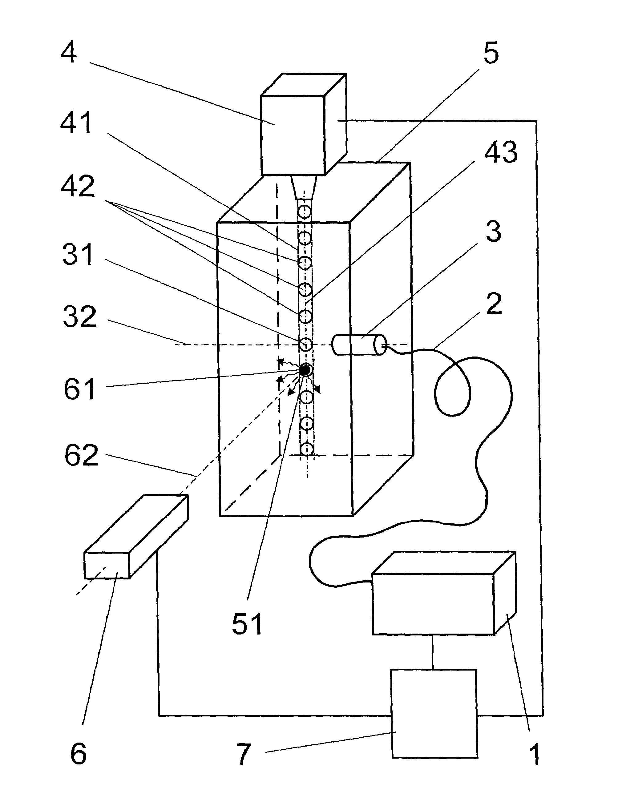
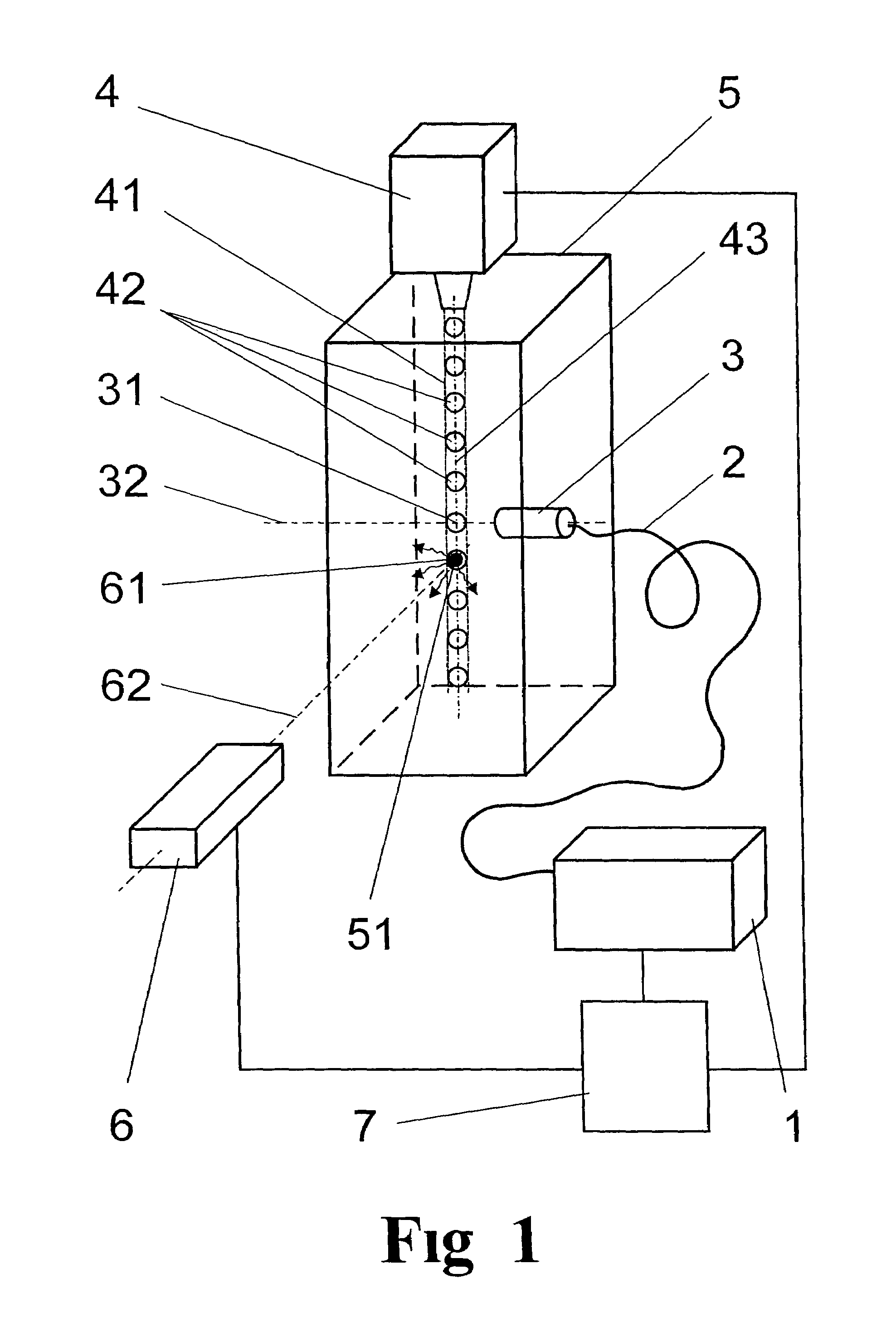
[0039]As is shown in FIG. 1, the arrangement basically comprises a detection module 1, a light waveguide 2, a projection module 3, and a target generator 4. The target generator 4 generates a target flow 41 whose path 43 traverses the interaction point 61 of an excitation laser 6 used for energy beam pumped plasma generation at a defined location within an interaction chamber 5 provided for the plasma generation.

[0040]Without limiting generality, a discontinuous flow of drops 42 will be shown and described in the following as a target flow 41 for plasma generation. However, it will be clear to the person skilled in the art that a discontinuous flow of solid targets as well as a continuous target flow 41 (et, such as is shown in dashes in FIGS. 1 and 3) is subject to the same conditions. A continuous target flow 41 is a simplified example of a flow of droplets 42 because the adjustment of constant excitation conditions for the excitation laser 6 at the continuous target flow 41 is st...


PUM


Abstract

The invention is directed to an arrangement for the optical detection of a moving target flow for pulsed energy beam pumped radiation generation based on a plasma. It is the object of the invention to find a novel possibility for detection of a moving target flow for energy beam pumped radiation generation based on a plasma which allows reliable orientation of the excitation beam on the target without the detector being subjected to influence and damage due to radiation emitted by the plasma. According to the invention, this object is met in that a target generator provides a target flow with relatively constant target states in an interaction point, a sensor unit is directed to a detection point which lies close to the interaction point in the direction of the path. The sensor unit contains a projection module which has a defined focal length and numerical aperture, so that only transmission light reflected from the detection point is received by the projection module and is directed via a light waveguide to the detection module which is arranged at a spatial distance, and the sensor unit also contains a detection module.

Description

CROSS-REFERENCE TO RELATED APPLICATION[0001]This application contains the priority of German Application No. 102 47 386.2, filed Oct. 8, 2002, the disclosure of which is hereby incorporated by reference.BACKGROUND OF THE INVENTION[0002]a) Field of the Invention[0003]The invention is directed to an arrangement for the optical detection of a moving target flow for pulsed energy beam pumped radiation generation based on a plasma, for example, for the generation of extreme ultraviolet radiation (EUV), soft x-ray radiation or particle radiation.[0004]b) Description of the Related Art[0005]When intensive laser radiation interacts with material, soft-x-ray radiation, particularly EUV radiation, and particle radiation, can be generated under defined conditions. For this purpose, intensive laser pulses are conducted to a solid, liquid or gaseous material (target) and generate in the latter a plasma which emits the desired radiation. When liquids are used as target material and introduced int...

Claims


Application Information

Patent Timeline
Patent Type & Authority Patents(United States)
IPC IPC(8): G01J3/30H05G2/00
CPCH05G2/008H05G2/003
Inventor STOBRAWA, GREGORBISCHOFF, MARKSAUERBREY, ROLANDZIEGLER, WOLFGANGRUEHLE, KLAUS
Owner USHIO DENKI KK
Learn More