Data transmission in packet-switched radio system implementing user equipment location service

a technology of user equipment and location service, which is applied in the direction of data switching networks, instruments, and eavesdropping prevention circuits, can solve the problems of not being able to implement not very much attention has been paid to implementing location services in packet-switched radio systems, etc., to achieve efficient implementation and avoid traffic load of support nodes.

Active Publication Date: 2006-06-27
NOKIA TECHNOLOGLES OY
View PDF19 Cites 15 Cited by
  • Summary
  • Abstract
  • Description
  • Claims
  • Application Information

AI Technical Summary

Benefits of technology

[0015]The method and apparatus of the invention provide several improvements. A radio network oriented solution becomes possible in GPRS. Communication between the user equipment and the serving mobile location center becomes possible. The solution re-uses existing solutions, i.e. it can be implemented efficiently. The traffic load of the support node does not increase, because the traffic coming from the user equipment is routed directly from the radio network to the serving mobile location center, and correspondingly, the traffic coming from the serving mobile location center is routed directly from the radio network to the user equipment. Existing GPRS systems can be updated with minimal changes to the system specifications to implement the location service.

Problems solved by technology

The problem is that if the cell in implemented by an omnidirectional antenna, the location of the user equipment is only known in relation to a base station on a circle drawn around it.
So far, not very much attention has been paid to implementing a location service to packet-switched radio systems, such as GPRS (General Packet Radio Service) or EGPRS (Enhanced General Packet Radio Service).
This is, however, not possible in packet-switched radio systems, because the serving mobile location center is in the radio network of the radio system, but the required third layers are in the core network of the radio system.

Method used


Image

  • Data transmission in packet-switched radio system implementing user equipment location service
  • Data transmission in packet-switched radio system implementing user equipment location service
  • Data transmission in packet-switched radio system implementing user equipment location service

Examples


Embodiment Construction

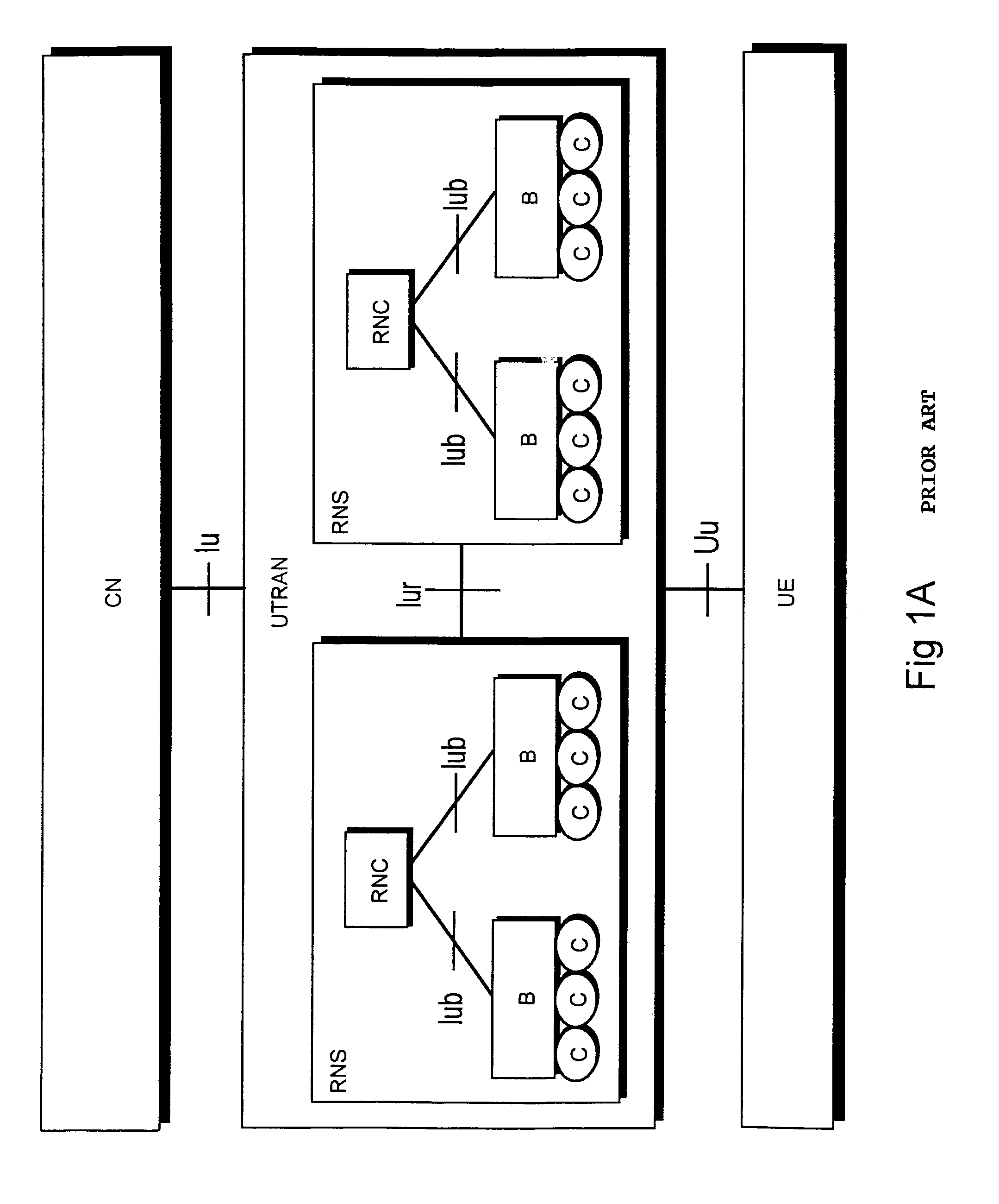
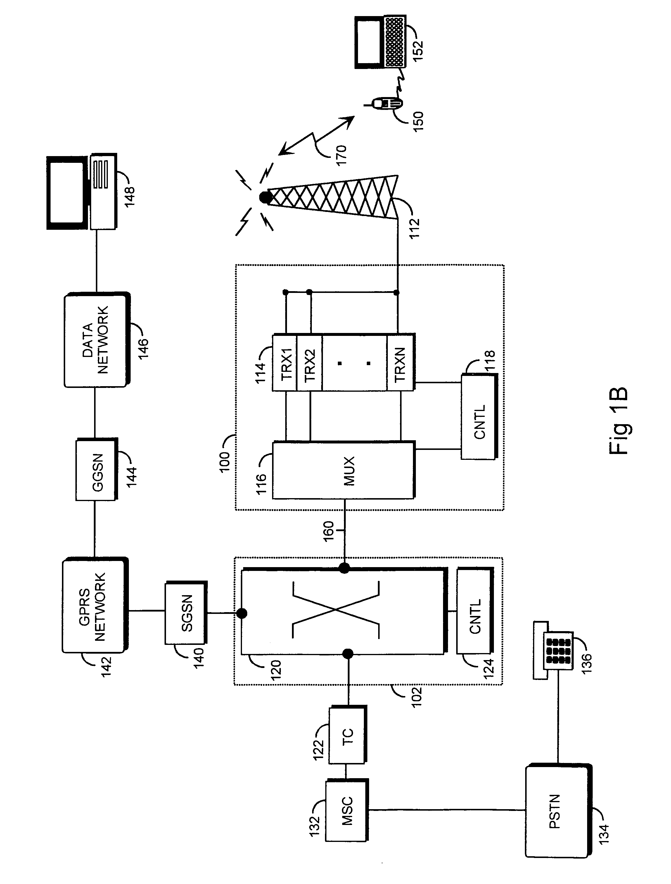
[0023]A typical structure of a packet-switched radio system and its interfaces to a public switched telephone network and a packet transmission network are described with reference to FIGS. 1A and 1B. FIG. 1B only shows the blocks essential to explaining the embodiments, but it is clear to a person skilled in the art that a conventional packet-switched cellular network also contains other functions and structures which need not be described in greater detail herein. The radio system can, for instance, be a GSM-based GPRS or EGPRS, a universal telecommunications system UMTS employing wideband code division multiple access, or an intermediate form of these systems, in which the structure of the radio network is outlined as in UMTS and the radio network is called GERAN (GSM Enhanced Radio Access Network), for instance, but in which the radio interface is, however, a GSM-based normal radio interface or a radio interface using EDGE modulation.

[0024]The description of FIGS. 1A and 1B is m...


PUM


Abstract

The invention relates to method and system for transmitting data between user equipment and serving mobile location center in packet-switched-radio system implementing user equipment location service. The method comprises: (302) data to be transmitted is placed in a message of a third-layer radio resource protocol; (304) the radio resource protocol message is transmitted to the radio network using a logical link control protocol set on the second layer of the packet protocol stack; (306) a logical link control protocol relay set on the second layer of the packet protocol stack in the radio network directs the logical link protocol message to a second party; (308) the second-layer logical link control protocol residing in the second party transmits the radio resource protocol message to the radio resource protocol set on the third layer; (310) the second party disassembles the transmitted data from the radio resource protocol message.

Description

FIELD[0001]The invention relates to a method for transmitting data in a packet-switched radio system implementing a user equipment location service, and to a packet-switched radio system implementing a user equipment location service.BACKGROUND[0002]Locating user equipment, i.e. defining the geographical location of user equipment, is an important function in cellular networks. In the United States, the Federal Communications Commission FCC requires that it must be possible to locate all user equipment making an emergency call to an accuracy of 50 meters. Location can also be utilized for commercial purposes, for instance for defining different tariff areas or for implementing a navigation service instructing a user. A location service (LCS) has until now been developed mainly for application to circuit-switched cellular networks, for instance the GSM system (Global System for Mobile Communications).[0003]Different methods are used in implementing a location service. On the roughest...

Claims


Application Information

Patent Timeline
Patent Type & Authority Patents(United States)
IPC IPC(8): H04J3/24H04Q7/20H04L12/56H04W64/00H04W80/04
CPCG01S5/0036G01S5/0205H04W80/04H04W64/00H04W4/12H04W4/029
Inventor VANTTINEN, VEIJO
Owner NOKIA TECHNOLOGLES OY
Why Eureka
Try Eureka