Optical fiber preform producing method, optical fiber production method, and optical fiber

a manufacturing method and technology for optical fibers, applied in the field of manufacturing methods for optical fibers, can solve the problems of difficult production of optical fiber preforms at high yields and high manufacturing costs, and achieve the effects of reducing the cost of optical fiber manufacturing processes, and improving the yield of glass preforms

Inactive Publication Date: 2006-06-27
SUMITOMO ELECTRIC IND LTD
View PDF9 Cites 5 Cited by
  • Summary
  • Abstract
  • Description
  • Claims
  • Application Information

AI Technical Summary

Benefits of technology

[0007]The optical fiber preform manufacturing method in the above way can manufacture the optical fiber preform at high precision because the glass rod containing the central core portion and the depressed portion each having the known refractive index profile is prepared, the glass pipe having the ring portion is prepared, and then the glass rod with the core and depressed portions is inserted into the glass pipe with the ring portion and integrated them (by rod-in-collapse).
[0044]With the conventional MCVD method, the starting pipe was the substantially pure silica pipe. For example, in fabricating a multilayer structure as shown in FIG. 12, the fluorine doped portion of the outer layer is conventionally synthesized by the MCVD method having low deposition rate. In this invention, the fluorine doped silica as the depressed portion on the outer circumference is employed as the starting pipe, and synthesized by the VAD method, the OVD method, or the outside deposition method with multiple burners to allow the fast glass synthesis, thereby remarkably increasing the productivity of the optical fiber.

Problems solved by technology

However, to fabricate a preform for optical fiber having a complex refractive index profile structure in which there are a plurality of maximal points and minimal points in the refractive index profile, such as a dispersion compensating fiber, a dispersion shifted fiber, or a dispersion flatted dispersion shifted fiber, the above manufacturing method for optical fiber preform has a problem that the optical fiber preform may be difficult to produce at high yield because the refractive index profile has a little tolerance for excellent characteristics.
Therefore, the preform for optical fiber with complex profile had a problem that the manufacturing cost may be high.

Method used


Image

  • Optical fiber preform producing method, optical fiber production method, and optical fiber
  • Optical fiber preform producing method, optical fiber production method, and optical fiber
  • Optical fiber preform producing method, optical fiber production method, and optical fiber

Examples


examples

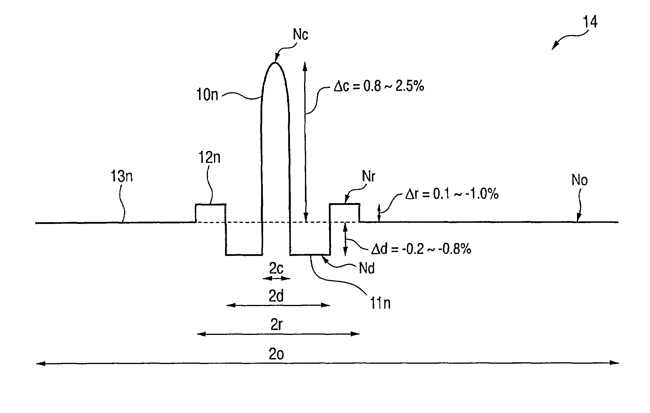
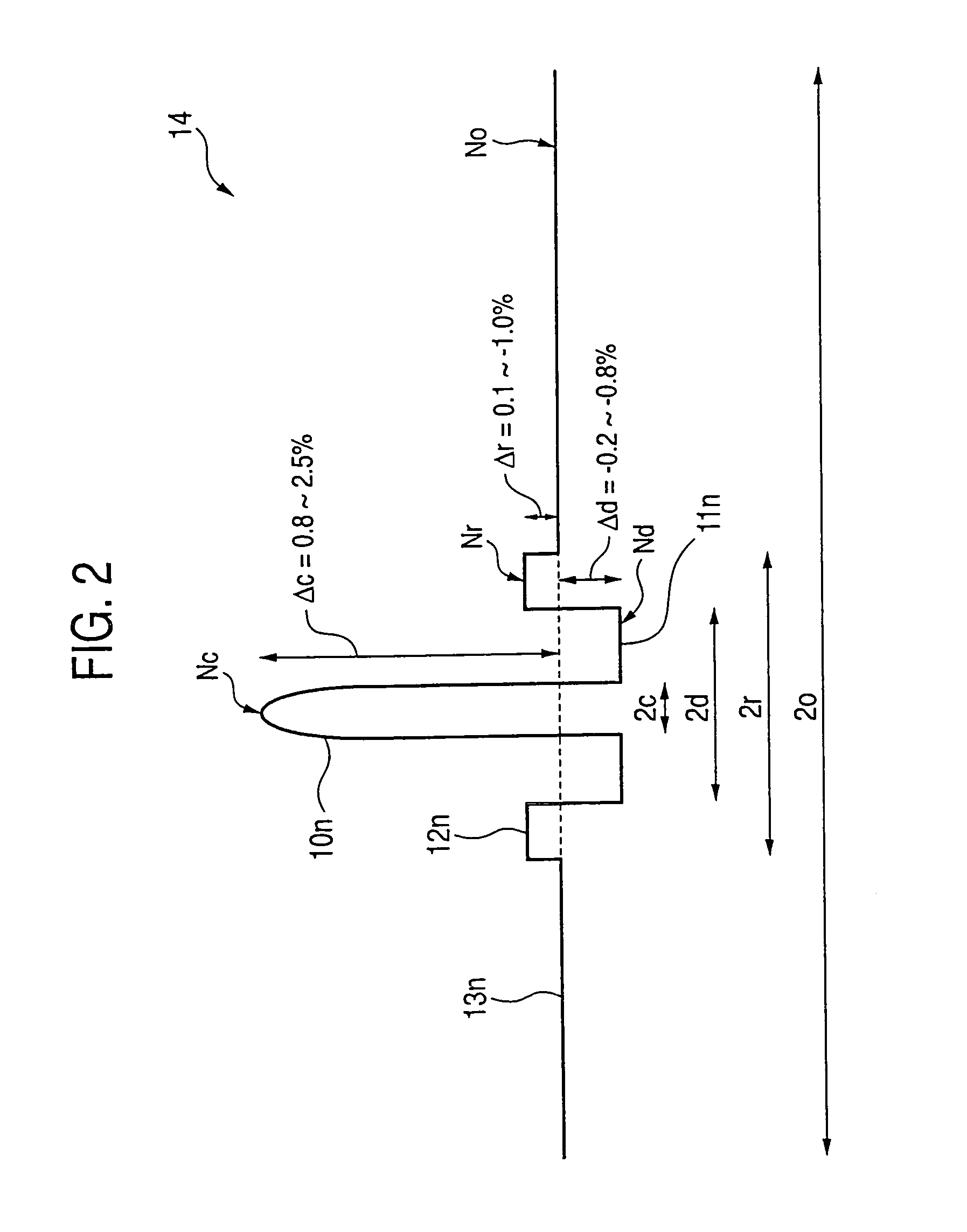
[0144]FIG. 20 shows a refractive index profile of an optical fiber as a first example which is obtained by the optical fiber preform manufacturing method and the optical fiber manufacturing method according to the invention. This example will be described below.

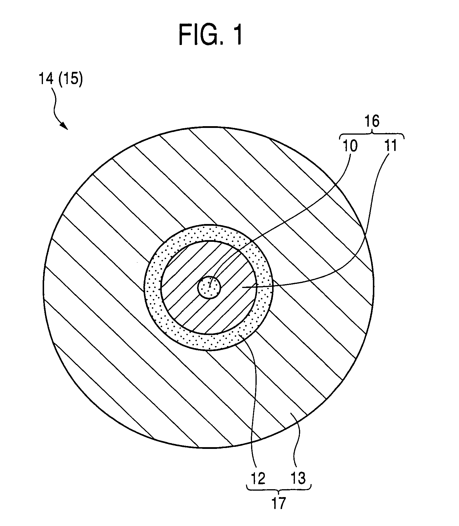
[0145]In this example, the obtained optical fiber was designed such that the outer diameter of the central core portion was 3.4 μm, the outer diameter of the depressed portion was 12.1 μm, the outer diameter of the ring portion was 15.7 μm, and the outer diameter of the outside cladding layer was 110.0 μm. In addition, the obtained optical fiber was designed such that the relative refractive index difference Δc of the central core portion to the outside cladding layer was 1.5%, the relative refractive index difference Δd of the depressed portion to the outside cladding layer was −0.5%, and the relative refractive index difference Δr of the ring portion to the outside cladding layer was 0.33%.

[0146]A glass rod A becoming the c...

third example

[0181]Next, a third example will be described below.

[0182]In this example, the manufacturing method for the optical fiber preform according to the first embodiment was employed.

[0183]First of all, the silica glass soot deposited by the OVD method was consolidated and elongated to fabricate a core rod. This core rod had an outer diameter of 4 mm or more, and the average value of outer diameter ellipticity in the whole length was 1% or less. A difference in deviation (eccentricity) between the center of refractive index profile and the center of outer diameter was made 1% or less.

[0184]Then, a silica glass pipe was prepared. This silica glass pipe had an outer diameter from 10 mm to 200 mm, and an inner diameter from 4 mm to 100 mm. In addition, the average value of eccentricity ratio of the pipe for the silica glass pipe in the whole length was made 1% or less, and the average value of the eccentricity was 1% or less. Moreover, the ellipticity of outer and inner diameter for the sili...

fourth example

[0195]Next, a fourth example will be described below.

[0196]In this example, the manufacturing method for the optical fiber preform according to the first embodiment was employed.

[0197]First of all, the silica glass soot deposited by the OVD method was consolidated and elongated to fabricate a core rod. This core rod had an outer diameter of 4 mm or more, and the average value of the whole length of outer diameter ellipticity was 1% or less. A difference in deviation (eccentricity) between the center of refractive index profile and the center of outer diameter was made 1% or less.

[0198]Then, a silica glass pipe was prepared. This silica glass pipe had an outer diameter from 10 mm to 200 mm, and an inner diameter from 4 mm to 100 mm. In addition, the average value of uneven thickness for the silica glass pipe was 1% or less, and the average value of eccentricity ratio of the pipe was 1% or less. Moreover, the ellipticity of outer and inner diameter for the silica glass pipe, and the a...


PUM

PropertyMeasurementUnit
lengthaaaaaaaaaa
wavelengthaaaaaaaaaa
outer diameteraaaaaaaaaa

Abstract

An optical fiber preform comprises a central core portion having a maximal value Nc of refractive index in the center, and outside the central core portion, comprising at least a depressed portion having a minimal value Nd of refractive index, a ring portion having a maximal value Nr of refractive index and an outside cladding layer having a maximal value No of refractive index. The optical fiber preform satisfies a relation of Nc≧Nr>No>Nd among the values of refractive index. A method of the optical fiber preform comprises fabricating a glass rod by inserting a rod containing at least the central core portion into a pipe containing at least the depressed portion and integrating them, fabricating a glass pipe having the ring portion, and fabricating a vitreous body by integrating the glass rod and the glass pipe by collapsing after inserting the glass rod into the glass pipe.

Description

TECHNICAL FIELD[0001]The present invention relates to a manufacturing method for an optical fiber preform, a manufacturing method for an optical fiber, and an optical fiber.BACKGROUND ART[0002]Conventionally, there are well-known methods for fabricating an optical fiber preform, including an MCVD method (Modified Chemical Vapor Deposition Method) and an OVD method (Outside Vapor Deposition Method). These methods involve synthesizing in succession a number of glass particle deposited layers radially on the inner or outer wall of a starting material of cylindrical or columnar shape to form a predetermined radial refractive index distribution (also referred to as a refractive index profile) and to fabricate a glass preform for drawing. Herein, the optical fiber preform means a vitreous body having substantially the same refractive index distribution as the optical fiber, in which an outside cladding layer may be further provided by such as a VAD method, an OVD method or a rod-in collap...

Claims


Application Information

Patent Timeline
Patent Type & Authority Patents(United States)
IPC IPC(8): G02B6/02G02B6/00C03B37/012G02B6/036
CPCC03B37/01211C03B37/0124G02B6/03688G02B6/03644G02B6/03666C03B2203/22C03B2203/29G02B6/02271C03B2203/36Y02P40/57C03B37/012G02B6/036
Inventor HIRANO, MASAAKIYANADA, EIJIYOKOKAWA, TOMOYUKISASAKI, TAKASHI
Owner SUMITOMO ELECTRIC IND LTD
Why Eureka
Try Eureka