
Striped braided element

a technology of braided elements and braided elements, which is applied in the direction of braids, textiles and paper, etc., can solve the problems of lack of structural rigidity supplied by fine wires, increase in the cost and complexity of medical devices of wires, and inability to be desirable, so as to improve the radio-opacity characteristics, improve the radio-opacity, and improve the radio-opacity

Inactive Publication Date: 2006-07-04
STRYKER CORP +1
View PDF7 Cites 91 Cited by
  • Summary
  • Abstract
  • Description
  • Claims
  • Application Information

AI Technical Summary

Benefits of technology

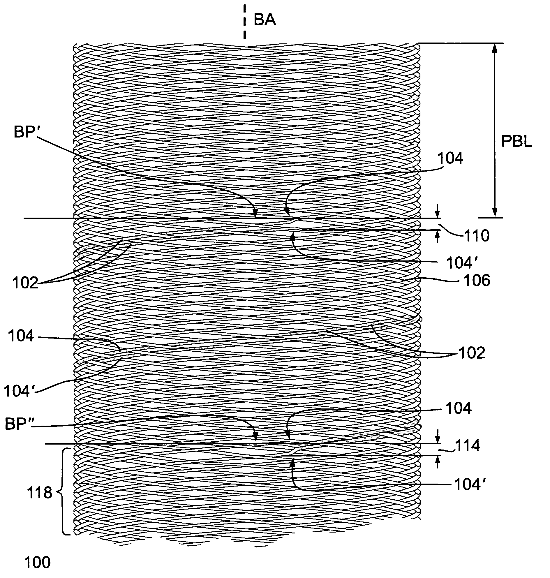
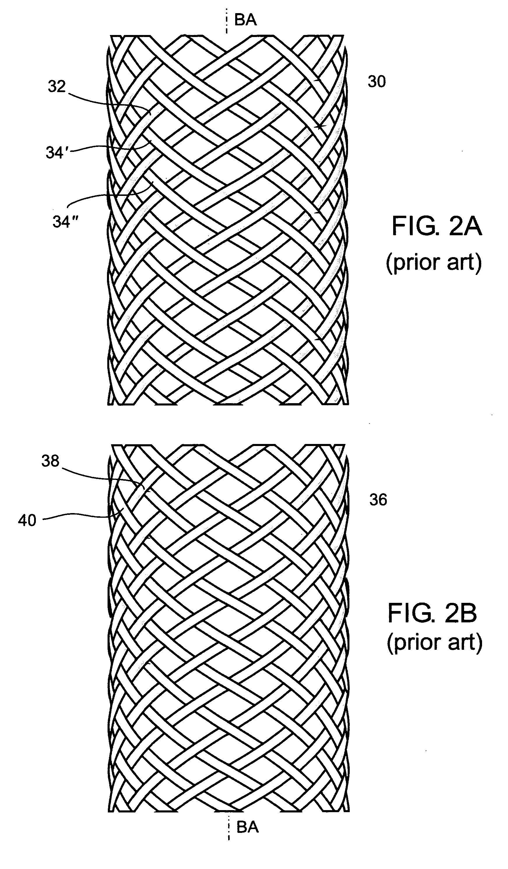
The present invention provides an improved method for producing a braided element with improved radio-opacity characteristics. The method allows for the adjustment of the radio-opacity characteristics at different points along the longitudinal axis of the braided element, with minimal effect on the regular braid pattern. The invention also allows for the production of different structural characteristics of the braided element, such as increased or decreased tension in certain members, or the production of stripes in a same pair of radial planes or cross-crossing stripes. The resulting braided element exhibits a uniform uninterrupted braid pattern and an average uniform distance between the center axis of members having a common direction of winding at a particular circumferential section along the common braiding axis. The invention also provides a striped braided element comprising a first set of members with a common direction of winding and a second set of members with an opposite direction of winding, with at least one stripe comprising two adjacent members of the same set exhibiting a significantly reduced distance between the center axis of the adjacent members.

Problems solved by technology

Unfortunately, such fine wire, in particular fine metallic wire having a cross-section or diameter smaller than approximately 100 μm, is relatively transparent to radiographic visualization.
Typically, these prior art solutions require the use of an additional material to be added to the intraluminal device, which may not be desirable.
Such a wire increases the cost and complexity of the medical device.
A further disadvantage to the prior art uniform braid pattern, particularly as applicable to a fine wire device, is the lack of structural rigidity supplied by the fine wire.
Unfortunately, utilizing multiple contiguous filaments increases the rigidity throughout the device, and does not allow for the possibility of having different combinations of rigidity at different points along the longitudinal axis.

Method used


Image

  • Striped braided element
  • Striped braided element
  • Striped braided element

Examples


first embodiment

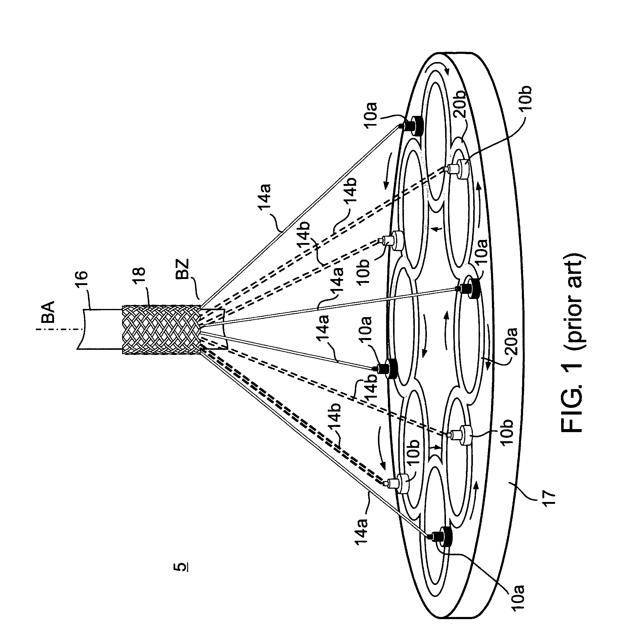
[0061]FIG. 4a illustrates the steps of the striped braiding method, according to the principles of the present invention. In step 1000 specific braiding operating parameters are selected, including but not limited to, type of filament to be braided, number of filament carrier units 10a, 10b number of filaments per member 14a, 14b, braiding angle or pitch, braiding speed and filament tension. The selection and implementation of operating parameters are well known to those skilled in the art. In an exemplary embodiment utilizing a 50 micron diameter wire, filament tension is set to about 1.5 Newtons with a horn gear braiding speed of approximately 75 RPM.

[0062]In step 1010 braiding machine 5 is operated to achieve a stable braiding point. After a stable braiding point has been achieved, optionally an initial non-striped braiding length is manufactured. Achieving a stable braiding point is accomplished solely for the purpose of ensuring stable operation, and is to be considered optiona...

second embodiment

[0066]FIG. 4b illustrates the steps of the generalized striped braiding method, according to the principles of the present invention. In step 1100 specific braiding operating parameters are selected, including but not limited to, type of filament to be braided, number of filament carrier units 10a, 10b, number of filaments per member 14a, 14b, braiding angle or pitch, braiding speed and filament tension. The selection and implementation of operating parameters are well known to those skilled in the art. In an exemplary embodiment utilizing a 50 micron diameter wire, filament tension is set to about 1.5 Newton with a braiding speed of approximately 75 RPM.

[0067]In step 1110 braiding machine 5 is operated to achieve a stable braiding point. After a stable braiding point has been achieved, optionally, an initial non-striped braiding length is manufactured. Achieving a stable braiding point is accomplished solely for the purpose of ensuring stable operation, and is to be considered opti...


PUM


Abstract

A striped braided element comprising: a first set of members having a common direction of winding, the center axis of said first set of members being axially displaced relative to each other in relation to a common braiding axis; and a second set of members having an opposite direction of winding, the center axis of the second set of members being axially displaced relative to each other in relation to the common braiding axis, the braided element exhibiting a uniform uninterrupted braid pattern and an average uniform distance between the center axis of members having a common direction of winding at a particular circumferential section along the common braiding axis; characterized by having at least one stripe comprising two adjacent members of the same set exhibiting a significantly reduced distance between the center axis of the adjacent members in the particular circumferential section.

Description

CROSS-REFERENCE TO RELATED APPLICATIONS[0001]This application claims priority from U.S. Provisional Patent Application Ser. No. 60 / 535,493 filed Jan. 12, 2004 entitled “METHOD FOR BRAIDING A STRIPED BRAIDED ELEMENT AND STRIPED BRAIDED ELEMENT FORMED THEREFROM” the entire contents of which are incorporated herein by reference.FIELD AND BACKGROUND OF THE INVENTION[0002]The present invention relates to braiding methods and braided elements formed therefrom, and more particularly, to a method for braiding a striped braided element and the striped braided element formed therefrom.[0003]The field of braiding, encompassing two-dimensional and three-dimensional braiding methods, devices, and systems, and braided elements formed by implementing thereof, is relatively well developed and documented about, including in the patent literature. Braiding is used in a wide variety of different fields, for example, textiles, electronics, aerospace, and medicine, for performing a variety of different ...

Claims


Application Information

Patent Timeline
Patent Type & Authority Patents(United States)
IPC IPC(8): D04C1/00D04C1/02
CPCD04C3/18D04C1/02D04C3/16
Inventor NISHRI, BOAZRAPAPORT, AVRAHAMCIBULSKI, GILADFOUKS, YANIV
Owner STRYKER CORP
Learn More