

Hydraulic control system for refuse collection vehicle
a technology of hydraulic control system and refuse collection, which is applied in the direction of transportation items, refuse collection, packaging goods type, etc., can solve the problems of low volumetric efficiency device, loss of energy into heat, and more heat and less useful work
- Summary
- Abstract
- Description
- Claims
- Application Information
AI Technical Summary
Benefits of technology
Problems solved by technology
Method used
Image

Examples
Embodiment Construction
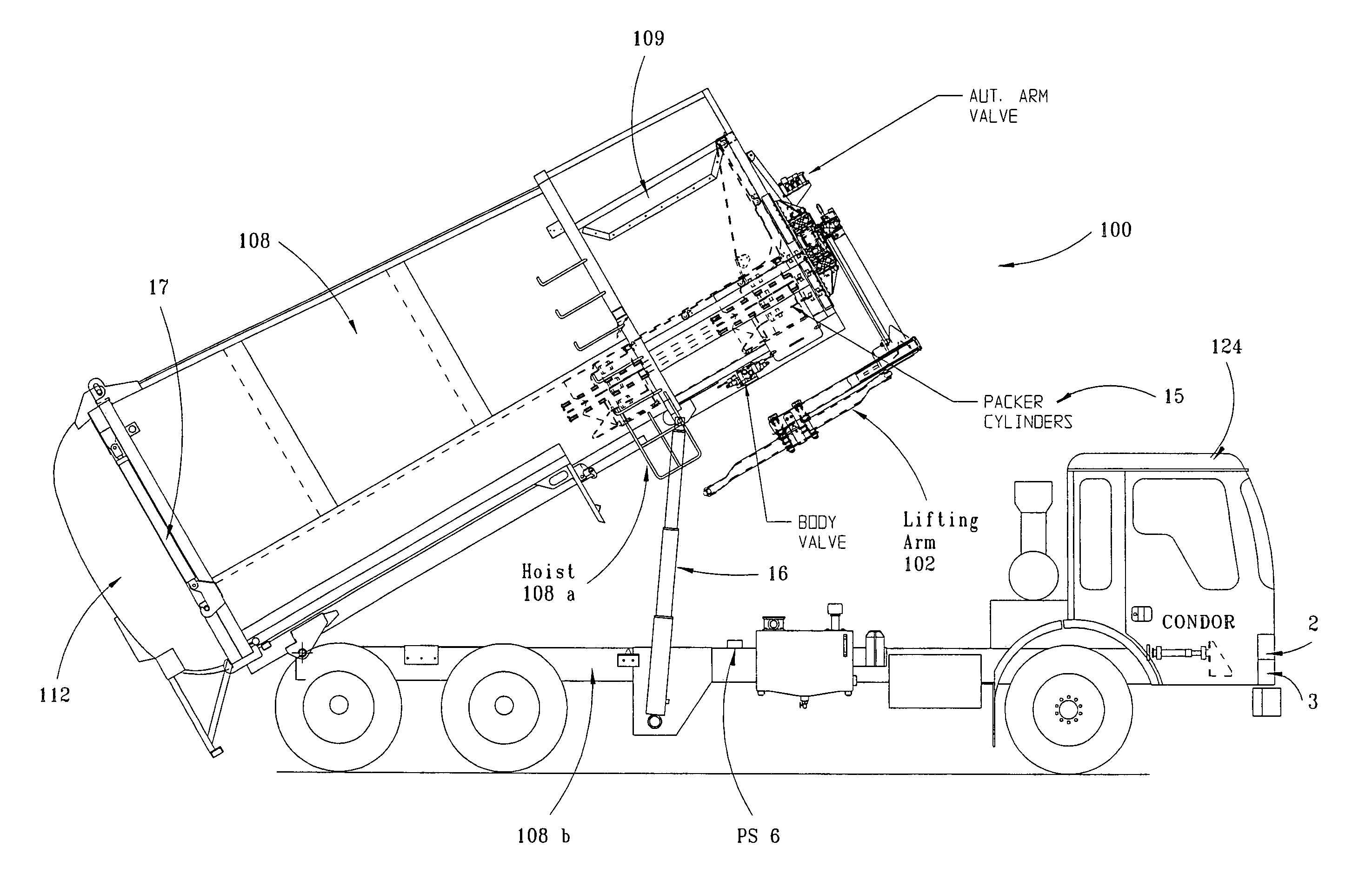
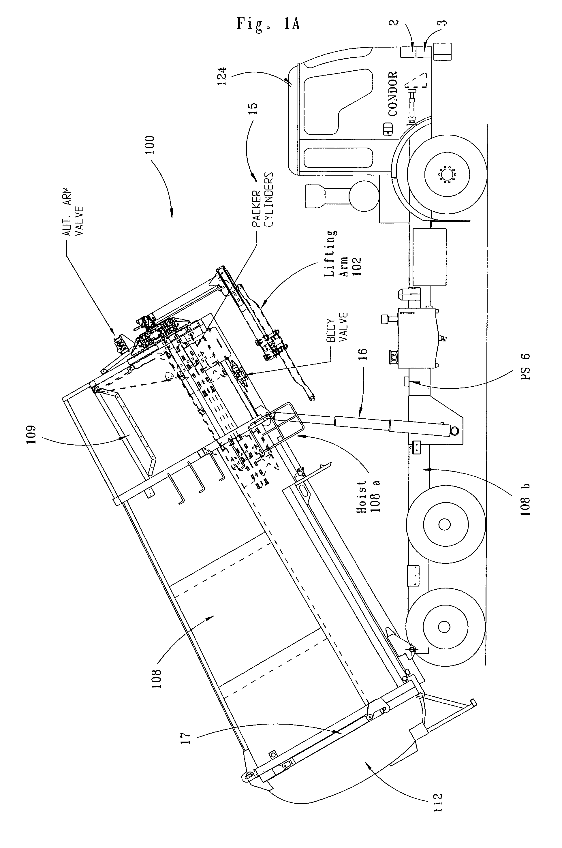
,” one will understand how the features of this invention provide its benefits. The benefits of this invention include, but are not limited to: (a) accurate and repeatable control of valve operations and speed of movement of drive mechanisms, in particular the accurate control of the speed of the lifting arm in a side loading or front loading refuse vehicle, (b) improved energy efficiency, (c) reduced wear of drive mechanisms, and (d) extended life of the hydraulic fluid.
[0010]Without limiting the scope of this invention as expressed by the claims that follow, some, but not necessarily all, of its features are:
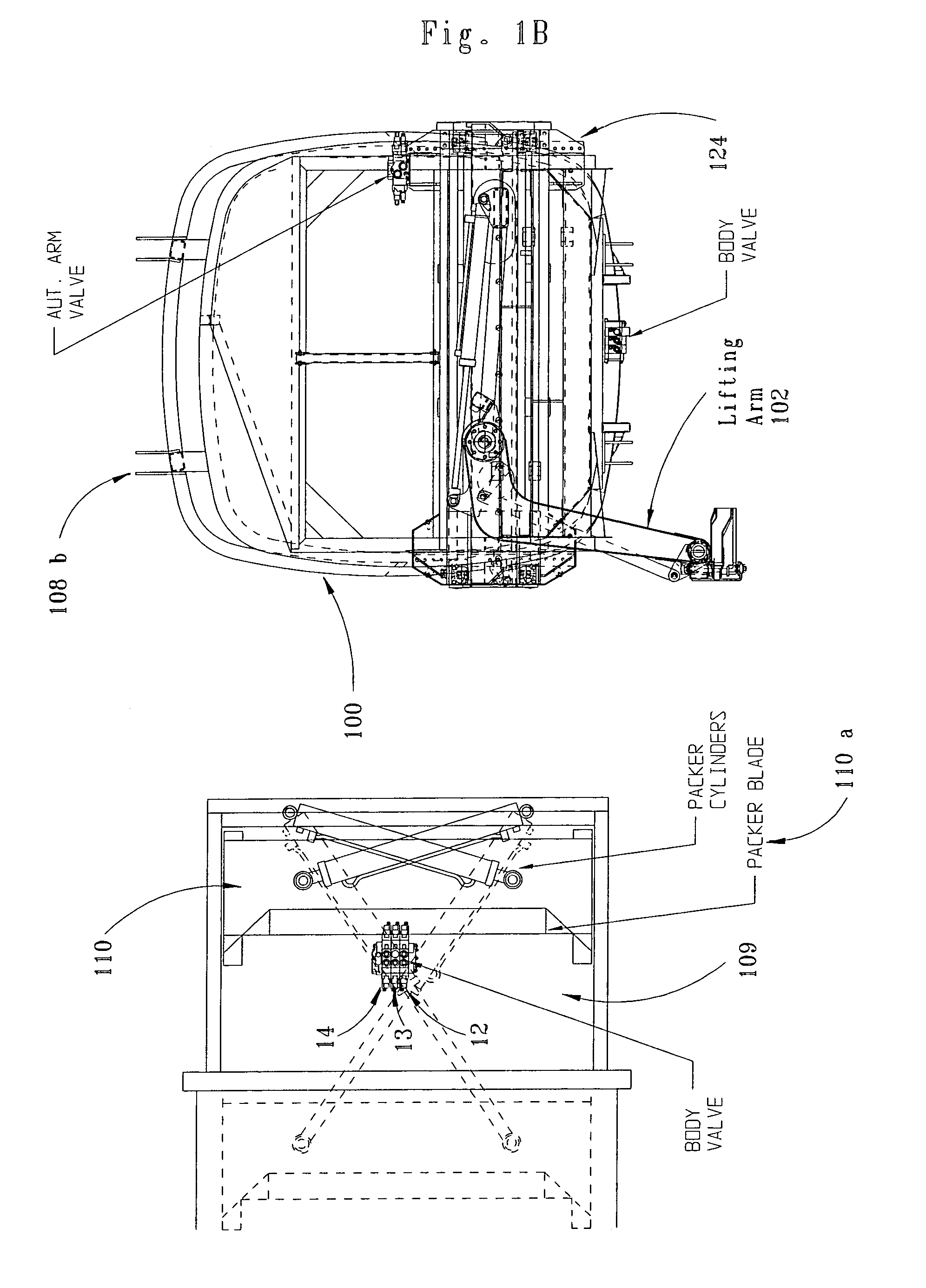
[0011]One, the refuse vehicle includes a lifting arm mounted to the vehicle that moves between a lowered position and a raised position. This arm may be mounted on the side or front of the vehicle.
[0012]Two, a refuse storage body is mounted to move between a lowered position and a raised position. It has a rear door that moves between a closed position and an open position, an...
PUM
 Abstract
Description
Claims
Application Information