Carbon media filter element

a filter element and carbon media technology, applied in the direction of filtration separation, separation process, colloidal chemistry, etc., can solve the problems of deficient structural integrity of prior sealing techniques, such as hotmelt techniques, vibration welding, etc., and achieve the effect of reducing the number of sintering holes

Active Publication Date: 2006-07-04
RBS CITIZENS N A +1
View PDF55 Cites 87 Cited by
  • Summary
  • Abstract
  • Description
  • Claims
  • Application Information

AI Technical Summary

Problems solved by technology

Prior sealing techniques, such as hotmelt techniques, vibration welding, etc., have been found deficient in not providing sufficient structural integrity.

Method used


Image

  • Carbon media filter element
  • Carbon media filter element
  • Carbon media filter element

Examples


Embodiment Construction

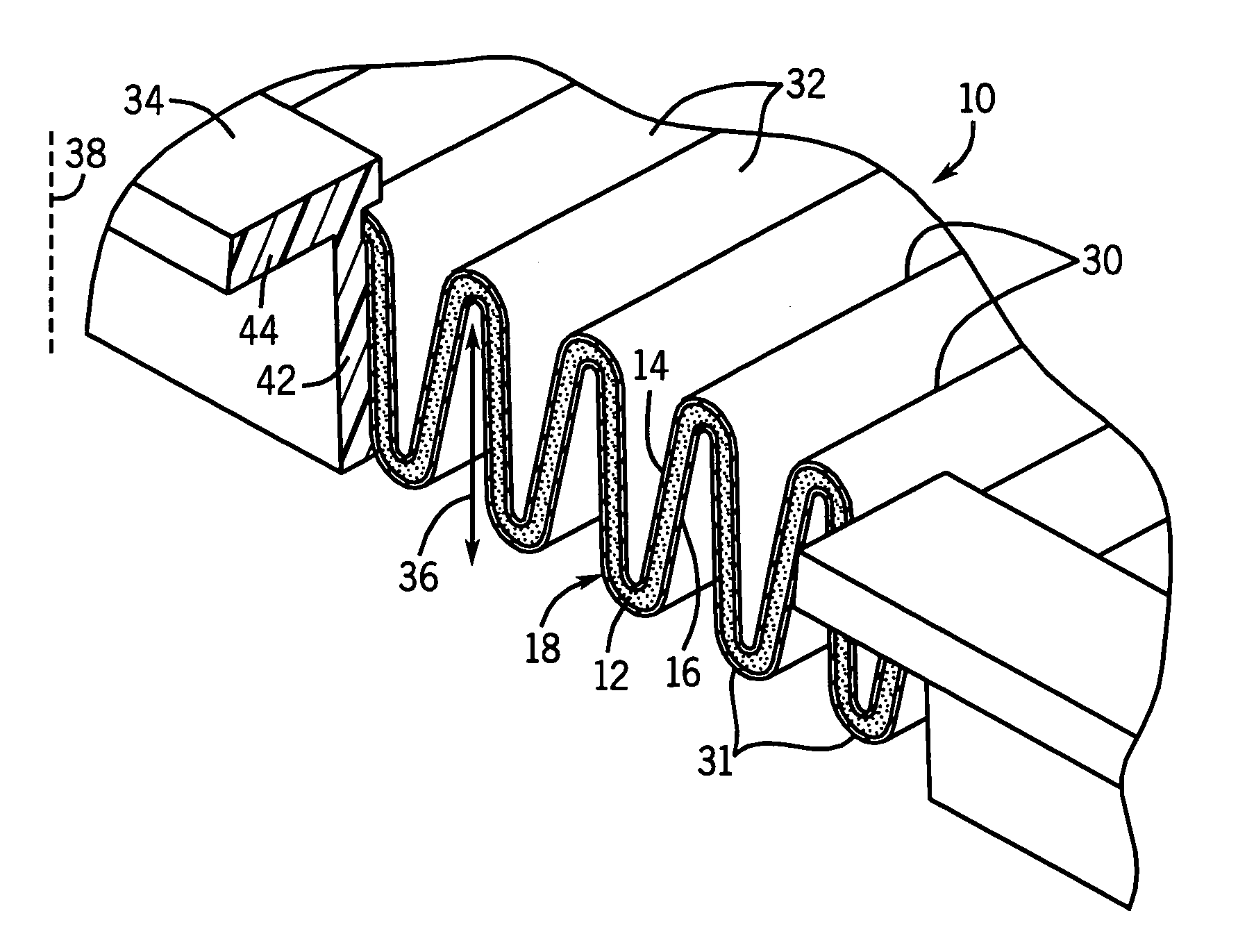
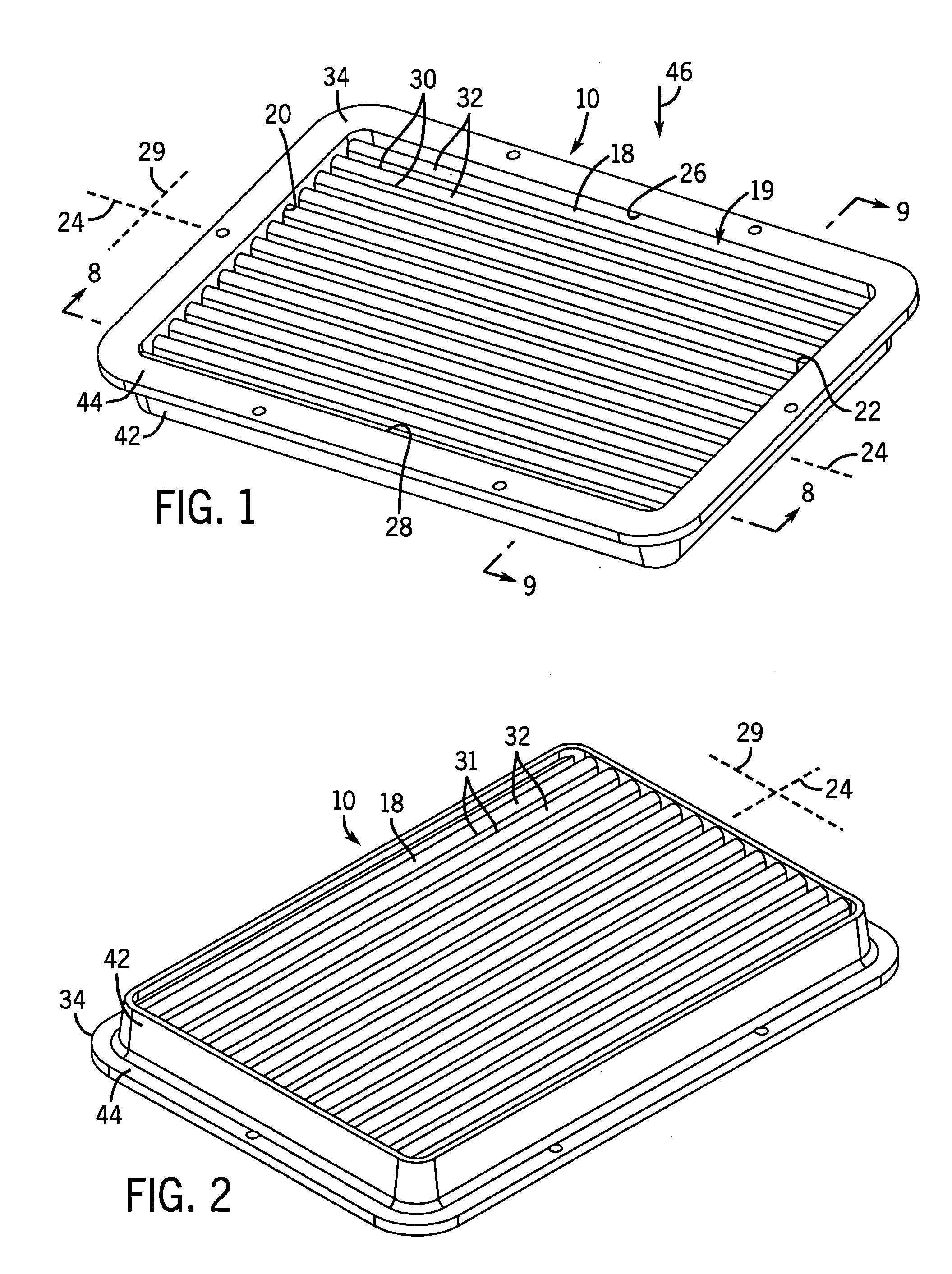
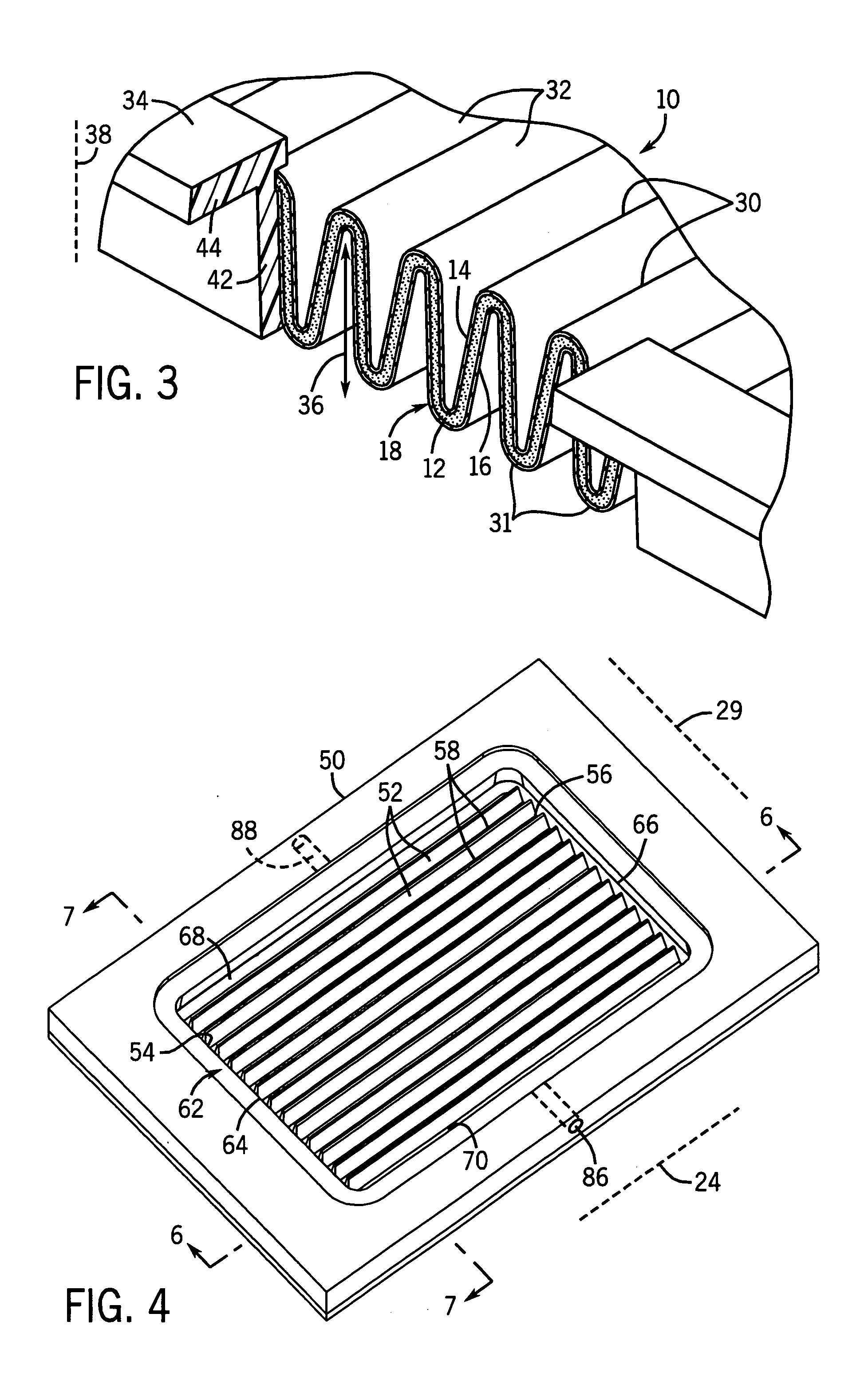
[0013]FIGS. 1–3 show a carbon media filter element 10 comprising a granular carbon layer 12, FIG. 3, sandwiched between first and second backing layers 14 and 16, and forming a sheet 18. The sheet has a perimeter 19 with first and second axial ends 20 and 22, FIG. 1, distally oppositely axially spaced along an axis 24, and first and second lateral ends 26 and 28 distally oppositely laterally spaced along lateral direction 29 relative to axis 24 and extending between axial ends 20 and 22. Sheet 18 is pleated along axially extending bend lines 30, 31 to provide a plurality of pleats 32 extending axially between axial ends 20 and 22. A border member 34 is composed of urethane and provides a combined structural frame and seal extending along perimeter 19 along ends 20, 26, 22, 28, and provides both the support frame for the carbon filter media and a seal along the ends of sheet 18 retaining carbon granules between backing layers 14 and 16 and preventing escape of carbon granules out of ...


PUM

PropertyMeasurementUnit
heightaaaaaaaaaa
inner perimeteraaaaaaaaaa
perimeteraaaaaaaaaa

Abstract

A carbon media filter element with urethane frame and seal has a border member composed of urethane providing a combined structural frame and seal extending along the perimeter and providing both the support frame for the media and a seal along the ends of the media sheet retaining carbon granules between backing layers and preventing escape of carbon granules out of the end. Manufacturing apparatus and methods are provided.

Description

BACKGROUND AND SUMMARY OF THE INVENTION[0001]The invention relates to carbon media filter elements, including for meeting automotive evaporative emission requirements in induction systems.[0002]Automotive manufacturers must meet ever decreasing evaporative emissions specifications for induction systems. It is known to incorporate a carbon media filter element in the engine intake system to meet the noted regulations. The carbon filter media is provided by a granular carbon layer sandwiched between first and second outer backing layers and formed in a pleated configuration. The ends of the pleats must be completely sealed to prevent escape of carbon granules out of such ends. Prior sealing techniques, such as hotmelt techniques, vibration welding, etc., have been found deficient in not providing sufficient structural integrity.[0003]The present invention provides an improved sealing and support system.BRIEF DESCRIPTION OF THE DRAWINGS[0004]FIG. 1 is a perspective view of a carbon med...

Claims


Application Information

Patent Timeline
Patent Type & Authority Patents(United States)
IPC IPC(8): B01D53/04
CPCB01D53/0415B01J20/20B01J20/28033B01J20/2804B01D2253/102B01D2253/34B01D2257/702B01D2258/01Y10S55/05B01D2259/4566Y10S55/31B01D2259/4516
Inventor GUNDERSON, LARRY T.SCHROEDER, ERICSCHROEDER, MARK C.FOSDAL, THOMAS A.JANIKOWSKI, ERIC A.
Owner RBS CITIZENS N A
Why Eureka
Try Eureka