Braking device for an electric motor, electrical apparatus provided with the braking device, and a method of braking

Active Publication Date: 2006-07-04
ROBERT BOSCH GMBH
View PDF16 Cites 25 Cited by
  • Summary
  • Abstract
  • Description
  • Claims
  • Application Information

AI Technical Summary

Benefits of technology

[0015]Moreover, preferably a handling sensor is provided, which in a power tool can recognize whether a power tool is hand-guided by the user or put down. A recognition of this different operational condition of the power tool is desirable since the braking process must be performed relatively fast when the power tool is put down, because then an increased injury danger takes place. If the user to the contrary holds the power tool with his hands, the running out time can be longer since the injury danger is then reduced. The handling sensor can be for example a simple switch which is integrated in the handle of the hand power tool and automatically actuated by the user of the hand power tool by holding the handle of the hand power tool.
[0016]In accordance with a preferable embodiment of the inventive braking device, a rotary speed sensor is further provided for detecting the rotary speed of the electric motor. The rotary speed sensor is connected with the control unit of the braking device so as to influence the braking process, depending on the rotary speed of the electric motor

Problems solved by technology

This poses for the user the dange

Method used


Image

  • Braking device for an electric motor, electrical apparatus provided with the braking device, and a method of braking
  • Braking device for an electric motor, electrical apparatus provided with the braking device, and a method of braking
  • Braking device for an electric motor, electrical apparatus provided with the braking device, and a method of braking

Examples


Embodiment Construction

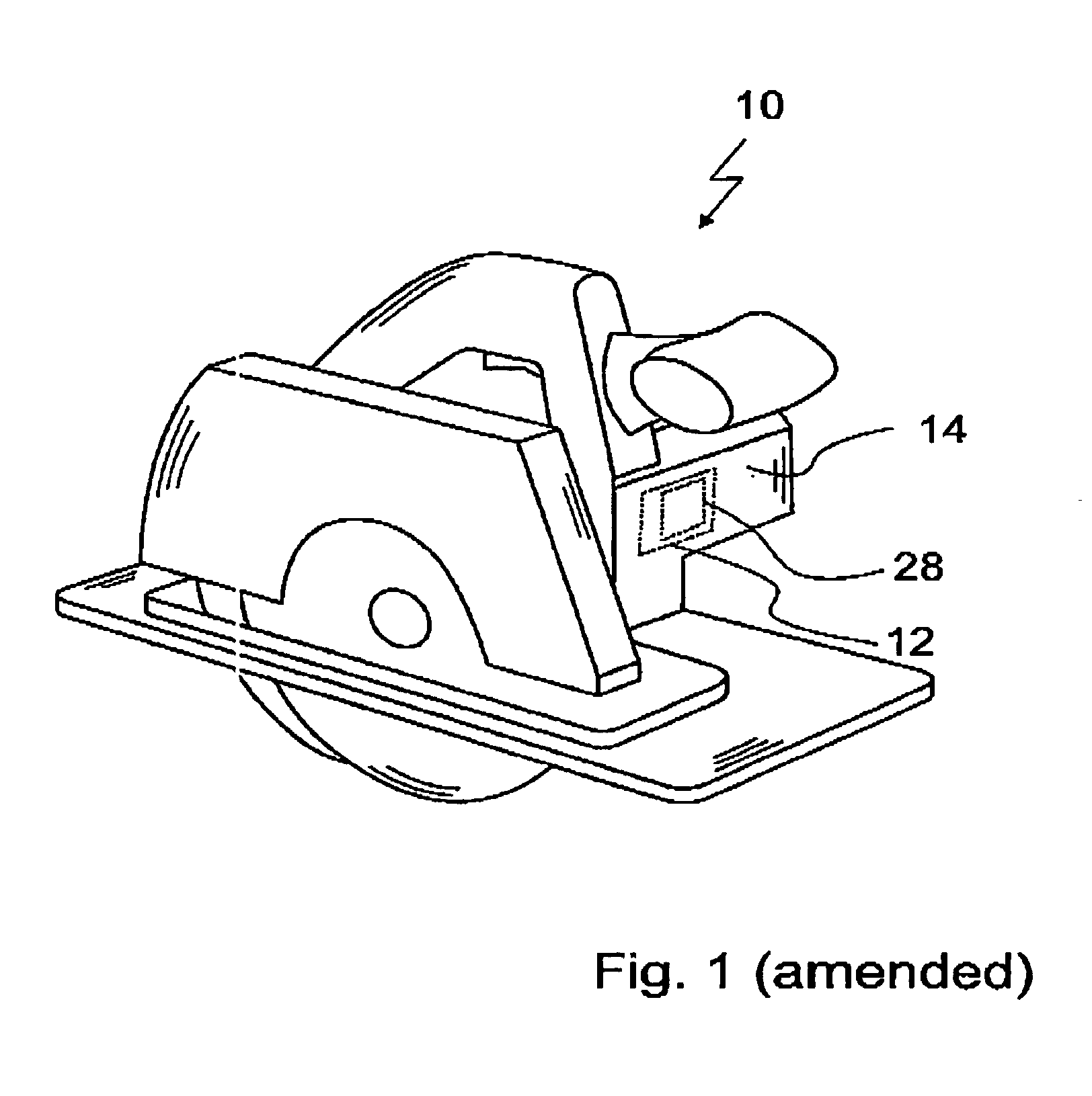
[0022]The perspective view in FIG. 1 shows a conventionally designed hand circular saw 10, and therefore a detailed description of the hand circular saw 10 can be dispensed with since it is disclosed in patent literature.

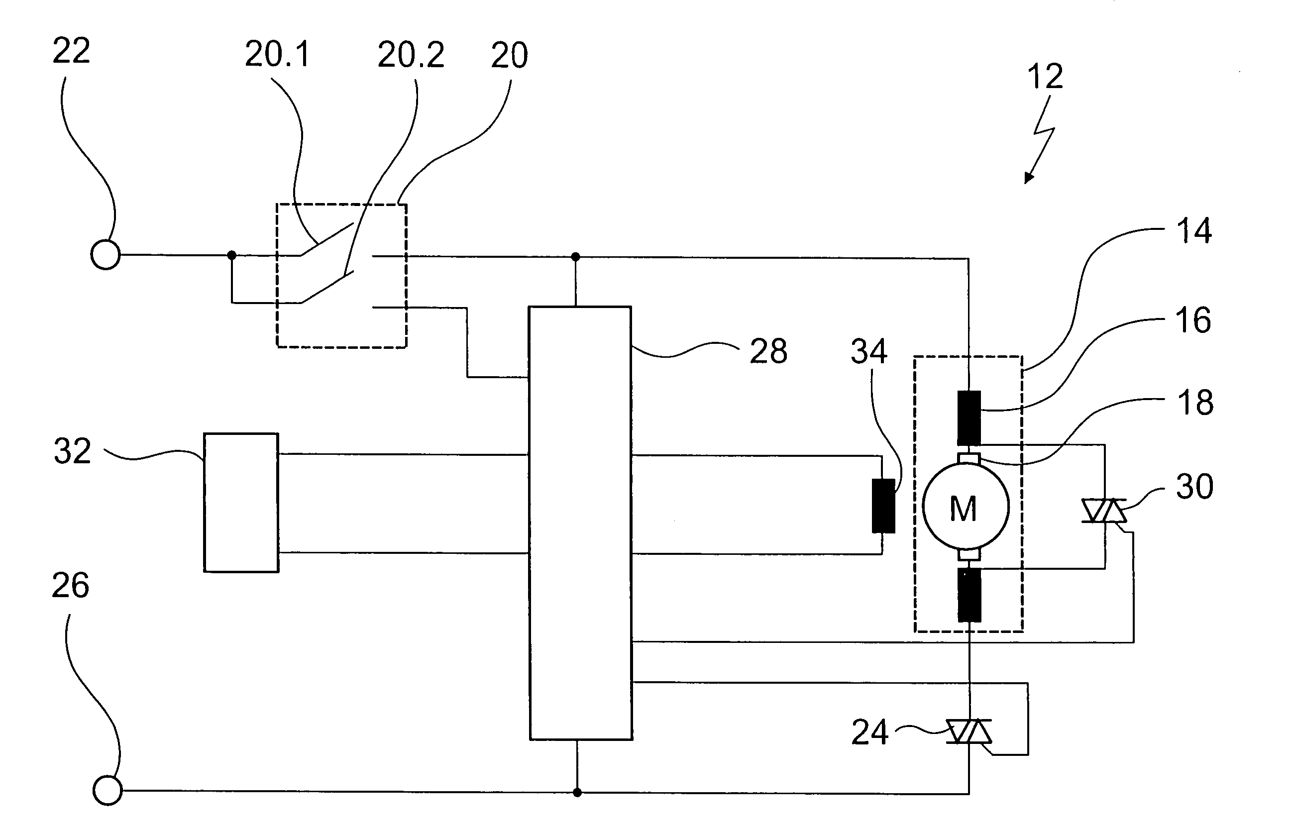
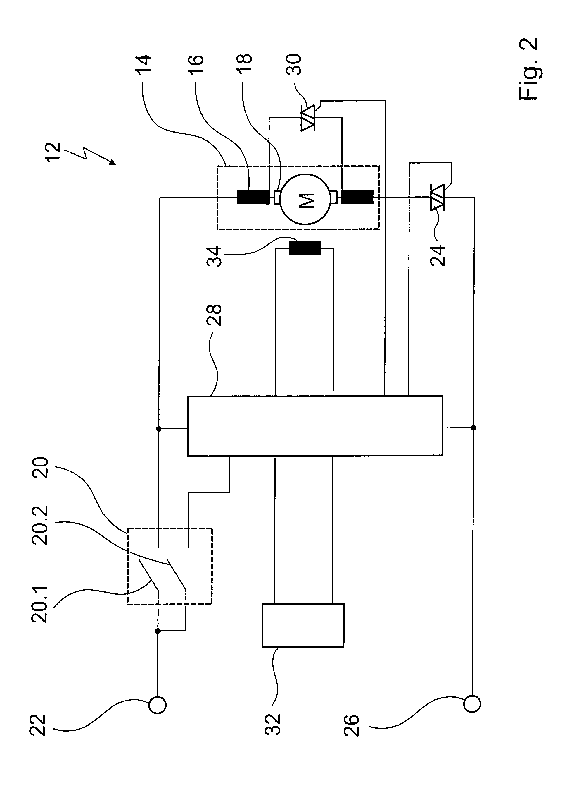
[0023]In accordance with the present invention, the hand circular saw 10 has a braking device which is identified with reference numeral 12. It is shown in FIG. 2 in form of a switching diagram and will be described in detail herein below.

[0024]The mechanical drive of the hand circular saw 10 is performed by a direct current serial motor 14 having a field winding 16 and an armature winding 18. The field winding 16 and the armature winding 18 are connected in series.

[0025]The drive current series motor 14 is connected through a delay switch 20 with a first connecting contact 22 and through a triac 24 with a second connecting contact 26. Both connecting contacts 22 and 26 are connected with a current supply in a conventional manner. Moreover, the braking device 12 has...


PUM


Abstract

A braking device for an electric motor of a power tool has a short circuit switch for short circuiting an armature winding of the electric motor during a braking process, the short circuit switch for controlling its switch condition having a control input, a control unit connected with the control input of the short circuit switch for performing a phase control of the short circuit switching during the braking process in order to avoid brush fire; also an electrical device with such a braking device and a braking method are proposed as well.

Description

BACKGROUND OF THE INVENTION[0001]The present invention relates to a braking device for an electric motor, in particular for an electric motor of a power tool. The present invention also relates to an electrical apparatus, such as for example a power tool, provided with a braking device. The invention also relates to a method of braking with the inventive braking device.[0002]Hand power tools such as for example power drills and hand circular saws are driven by direct current series motors, which are identified as universal motors.[0003]When such hand power tools are turned off, the direct current series motor, due to the mechanical inertia of the drive train, does not stop. This poses for the user the danger of an injury during running out.[0004]For reducing this injury danger it is suggested in the European patent document EP0578366 A2 to provide a braking device for a direct current series motor, in which the armature winding of the direct current series motor can be short circuit...

Claims


Application Information

Patent Timeline
IPC IPC(8): H02P3/12H02P3/22
CPCH02P3/12
Inventor HAHN, DIETMARWALTER, ROLAND
Owner ROBERT BOSCH GMBH
Why Eureka
Try Eureka