Power circuit and method for controlling same

a power circuit and power supply technology, applied in the direction of electric variable regulation, process and machine control, instruments, etc., can solve the problems of increasing the amount of power consumed, the size of the terminal of the portable device, and the capacity of the cell being used as a power source, so as to improve the safety required for using the primary cell, the effect of improving the discharging efficiency of the cell

Inactive Publication Date: 2006-07-04
TOKIN CORP
View PDF5 Cites 21 Cited by
  • Summary
  • Abstract
  • Description
  • Claims
  • Application Information

AI Technical Summary

Benefits of technology

[0044]With the above configurations, in the power circuit having a direct current power source as a power source, by placing an energy storing section on an output side of the current limiting section adapted to exert output current control and output voltage control in order to accommodate a change in the load current, even in the case of a load in which its current flows periodically and alternately in a burst-period and a non-burst period, a peak value of a power current can be made smaller. By making a peak value of a power current, in the case where the power source section is a cell, discharging life of the cell can be extended. Moreover, even in the case of a power source whose output current has an upper limit value, in the case of a load in which, though power consumption exceeds an upper limit value only during a burst period, average power consumption is less than power supplied from the power source, the power circuit can be driven. Moreover, in the case where the load, though consuming a constant power in an ordinary manner, provides a current pattern in which a burst period and a non-burst period occur alternately and periodically, since an upper limit value of a set current can be changed automatically according to a power voltage, even if the load consumes constant power, so long as it is a periodical pulse, the effect described above can be obtained.
[0050]According to the present invention, when a load is driven in which power consumption is periodically changed, in the case of using a chemical cell as a power source, it is made possible to lengthen operation time by improving discharging efficiency of a cell or, in the case of using a power source whose most upper output current is limited, even if power consumption of a device exceeds an upper limit value within a set period of time, driving of a device is made possible.
[0051]Also, according to the present invention, the above effect can be improved using a method in which setting of an upper limit value of a power current is changed.
[0052]Moreover, in the case of using a chemical cell as a power source, a primary cell or a secondary cell is used. In this case, by introducing a charging preventing device to prevent a primary cell from being erroneously charged, safety required for using the primary cell can be improved. Two types of units having functions of controlling a power source can be used in the power circuit of the present invention, one functioning singly as an output current limiting device and another functioning as both an output current limiting device and an output voltage limiting device, which has improved versatility so as to be able to meet different types or natures of a load current.

Problems solved by technology

On the other hand, as terminals of portable devices become multifunctional, an amount of power being consumed tends to increase and therefore it is required that a cell being used as a power source has a large capacity.
However, such a large capacity of a cell serving as a power source leads to a larger scale of and a larger weight of terminals of portable devices, which become contradictory to a demand for being made smaller and lightweight being required for terminals of portable devices to improve performance.
To satisfy such contradictory demands in terminals of portable devices, a cell having higher energy density or having lower internal impedance is being developed, however, such presently available contrivance does not achieve a satisfactory result.
However, in the case of such portable devices in which their loads vary with time which is specific to digital devices prevailing in recent years as devices operating according to a TDMA (Time Division Multiple Access) method, digital data transfer systems, or likes, since their cell voltage changes over time, matching between the lowest driving voltage and the discharge terminating voltage becomes difficult and therefore a conventional power source circuit has a problem in that it cannot operate a cell fully effectively.
Moreover, in the case of devices being supplied with source power from a personal computer, or the like, serving as a host according to a USB (Universal Serial Bus) with specifications for the Internet, there is a problem in that, since an upper limit is imposed on a current that can be employed in the USB, devices that consume a current exceeding the upper limit can not be used.
Thus, a conventional power circuit presents a problem in that effective use of a cell serving as a power source is impossible and devices consuming a current exceeding such a limit value cannot be used.

Method used


Image

  • Power circuit and method for controlling same
  • Power circuit and method for controlling same
  • Power circuit and method for controlling same

Examples


first embodiment

[0067]Next, detailed configurations of the power circuit having the first basic configuration are further described.

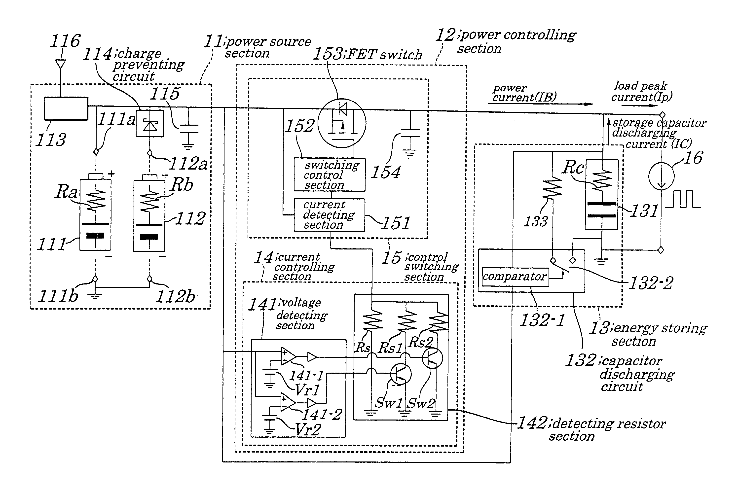
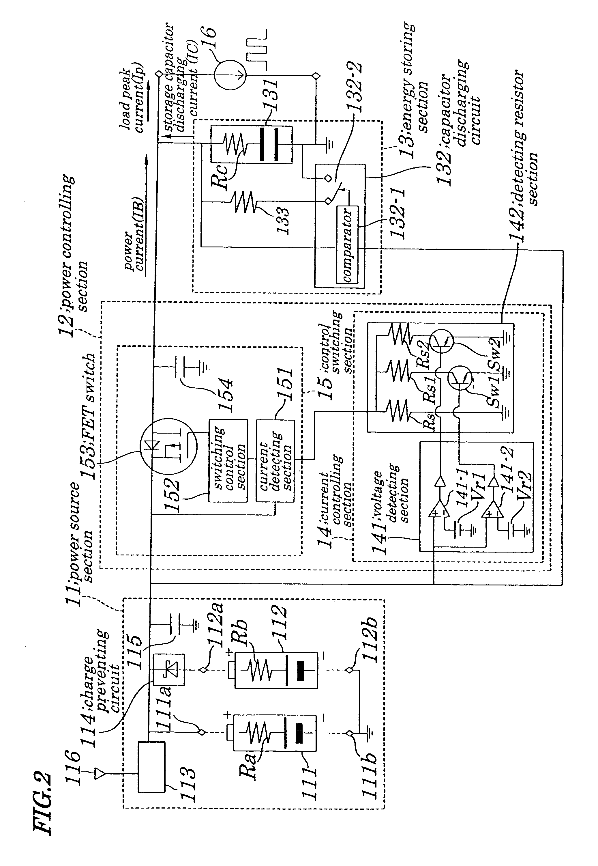
[0068]FIG. 2 is a circuit diagram for showing a concrete configuration of the power circuit of the first embodiment. FIG. 3 is a time chart illustrating operations of the power circuit of the first embodiment. FIG. 4 is a diagram explaining an effect of an extension of a life of a cell in the power circuit of the first embodiment.

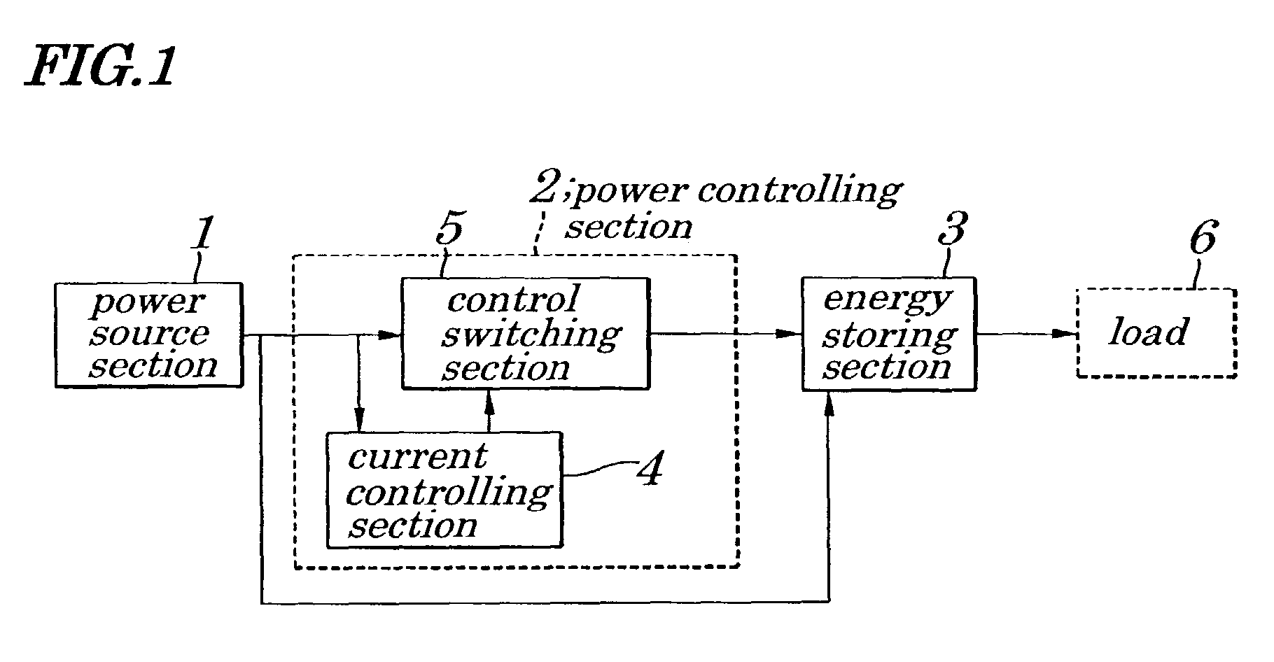
[0069]The power circuit of the first embodiment, as shown in FIG. 2, chiefly includes a power source section 11, a power controlling section 12, and an energy storing section 13. The power controlling section 12 is made up of a current controlling section 14 and a control switching section 15.

[0070]The power source section 11 is a direct current power source using a chemical cell and makes up a cell holder that can house a secondary cell 111 or a primary cell 112. The power source section 11 further includes a secondary cell charging circuit 1...

second embodiment

[0109]FIG. 6 is a circuit diagram showing a concrete configuration of a power circuit according to a second embodiment of the present invention.

[0110]The power circuit of the embodiment, as shown in FIG. 6, chiefly includes a power source section 11, a power controlling section 12A, and an energy storing section 13. Of them, configurations of the power source section land the energy storing section 3 are same as those employed in the power circuit having the first basic configuration shown in FIG. 2.

[0111]The power controlling section 12A is made up of a current controlling section 14A adapted to produce a control signal to control a current output from the power source section 11 and a control switching section 15A adapted to control a current according to a control signal fed from the current controlling section 14A and to control a voltage output to the load 16. The current controlling section 14A is made up of a voltage detecting circuit 143 having a plurality of detectors 143-1...

third embodiment

[0122]Next, configurations of the power circuit based on the second basic configurations of the present invention will be described in detail.

[0123]A power circuit according to a third embodiment of the present invention, as shown in FIG. 7, chiefly includes a power source section 11, a power controlling section 12B, and an energy storing section 13. Of them, configurations of the power source section 11 and the energy storing section 13 are the same as in the case of the first embodiment as shown in FIG. 2.

[0124]The power controlling section 12B is made up of a current controlling section 14B adapted to produce a control signal to control a current output from the power source section 11 and a control switch section 15B adapted to control a current according to a control signal fed from the current controlling section 14B and to control a voltage output to the load 16.

[0125]The current controlling section 14B is made up of a voltage detecting circuit 145 having a plurality of detec...


PUM


Abstract

A power circuit is provided which has a small current peak value from a power source even when a load current repeats periodically, and a burst flow in a burst period and a non-burst flow in a non-burst period alternates. The power circuit includes a power source section, a power controlling section, and an energy storing section having a storage capacitor being connected to an output terminal, a current controlling circuit to control values of detecting a voltage input from a power source section and a control switching device having a field effect transistor switch and a circuit made up of a capacitor in which a flowing period of an output current is controlled by exerting the field effect transistor switch according to a control signal being produced by detecting a change in an input power voltage using a voltage occurring at another terminal of the detecting resistor.

Description

BACKGROUND OF THE INVENTION[0001]1. Field of the Invention[0002]The present invention relates to a power circuit and a method for controlling the power circuit being capable of making a peak value of a source current adapted to supply source power to a load in which its power consumption changes periodically and of allowing an amount of a current drain to exceed an upper limit value within a set period of time.[0003]The present application claims priority of Japanese Patent Application No. 2002-045219 filed on Feb. 21, 2002, which is hereby incorporated by reference.[0004]2. Description of the Related Art[0005]In recent years, as terminals of portable devices become multifunctional to achieve connections or access to the Internet, distribution of moving pictures, or a like, both a transmission speed and an amount of data communications tend to increase. Moreover, it is essential that these terminals of portable devices be made not only multifunctional but also smaller and more light...

Claims


Application Information

Patent Timeline
Patent Type & Authority Patents(United States)
IPC IPC(8): G05F1/56G05F1/618H02J7/00H02J7/34H02M3/155
CPCH02J7/345H02M3/07
Inventor SASAKI, HIROSHI
Owner TOKIN CORP
Why Eureka
Try Eureka