Anisotropic, conductive sheet and impedance measuring probe

a technology of conductive sheets and impedance measuring probes, applied in the direction of connection contact materials, coupling device connections, instruments, etc., can solve the problems of increasing the unnegligible level, the transmission of desired data signals may not become infeasible, and the performance requirements of printed wiring boards for transmitting data signals between cpu and external apparatus

Inactive Publication Date: 2006-07-04
ISC CO LTD
View PDF9 Cites 54 Cited by
  • Summary
  • Abstract
  • Description
  • Claims
  • Application Information

AI Technical Summary

Benefits of technology

[0018]A second object of the present invention is to provide an impedance-measuring probe, which can prevent a board to be measured from being damaged upon impedance measurement and can achieve high reliability on measurement in a high-frequency region of at least 1 GHz, particularly a high-frequency region of at least 10 GHz.[Means for Solving the Problems]
[0143]According to the impedance-measuring probe 120 provided with this anisotropically conductive sheet 80, a surface (upper surface in FIG. 10) of the anisotropically conductive sheet 80, which is opposed to the surface connected to the impedance-measuring probe body 120, is brought into contact with a printed wiring board that is a board to be measured and pressurized, whereby a circuit to be measured of the printed wiring board is connected to the measuring circuit 121 of the impedance-measuring probe body 120A, and moreover a reference ground circuit of the printed wiring board is connected to the ground circuit-connecting circuit 122 of the impedance-measuring probe body 120A through the respective conductive parts (conductive part K and conductive part G) of the anisotropically conductive sheet 80, thereby achieving conduction to perform measurement of impedance.

Problems solved by technology

The operating clock frequency increases as described above, whereby requirements for the performance of a printed wiring board for transmitting data signals between CPU and the external apparatus become severe.
When mismatching is present between the characteristic impedances of printed wiring circuits electrically connected to each other or between the characteristic impedance of a printed wiring circuit and the impedance of a circuit load electrically connected to this printed wiring circuit, a part of data signals are reflected into a signal-transmitting source, whereby a signal finally directing to a circuit load is weakened to cause a problem that there is a possibility that transmission of desired data signals may not become infeasible.
Such a problem becomes more marked to an unnegligible level as the operating clock frequency becomes higher.
In the conventional impedance-measuring probes, however, a conduction state is created by pressing the pointed contact pins against the signal circuit and ground circuit of a printed wiring board, so that the printed wiring board may be damaged upon measurement of its impedance.
In addition, since the contact pins made of a metal are brought into contact with the signal circuit and ground circuit of the printed wiring board, there is a problem that reliability on measurement is low in that a contact state between the impedance-measuring probe and the printed wiring board is unstable.
It has thus been difficult to exactly measure impedance by the conventional impedance-measuring probe.
However, there is a possibility that the conventional impedance-measuring probes may not sufficiently cope with such a demand.
However, the conventionally known anisotropically conductive sheets have involved such problems that a transmission loss becomes great when they are used in a high-frequency region, and so they have been unable to bring about sufficient properties in the impedance measurement in the high-frequency region, and have undergone difficulty in use in practice.

Method used


Image

  • Anisotropic, conductive sheet and impedance measuring probe
  • Anisotropic, conductive sheet and impedance measuring probe
  • Anisotropic, conductive sheet and impedance measuring probe

Examples


example 1

[0184]To 100 parts by mass of addition type liquid silicone rubber, “KE2000-60” (product of Shin-Etsu Chemical Co., Ltd.), were added 22.5 parts by mass of magnetic conductive particles having an number average particle diameter of 8 μm and 2.5 parts by mass of sodium alkylsulfonate (CnH2n+1SO3Na (n=12 to 20)) to mix them, thereby preparing a sheet-molding material.

[0185]In the above-described process, composite particles (average amount coated: 7% by weight of the weight of core particles) obtained by plating core particles formed of nickel with gold were used as the magnetic conductive particles.

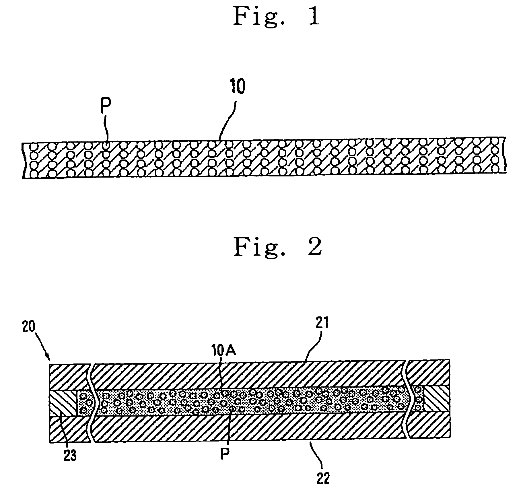
[0186]The sheet-molding material thus prepared was filled into a mold having the construction illustrated in FIG. 2 and equipped with a spacer having a thickness of 30 nm, thereby forming a sheet-molding material layer.

[0187]The sheet-molding material layer formed between a top force and a bottom force, which were each made of a ferromagnetic substance plate, was then subjected to a curing...


PUM

PropertyMeasurementUnit
thickness W1aaaaaaaaaa
thickness W2aaaaaaaaaa

Abstract

An anisotropically conductive sheet of the invention formed by containing conductive particles exhibiting magnetism in a sheet base composed of an elastic polymeric substance in a state dispersed in a plane direction thereof and oriented so as to align in a thickness-wise direction thereof. A thickness of the sheet is 10 to 100 μm, a number average particle diameter of the conductive particles exhibiting magnetism is 5 to 50 μm, a ratio W1 / D of the thickness W1 to the number average particle diameter D of the conductive particles exhibiting magnetism is 1.1 to 10, a content of the conductive particles exhibiting magnetism is 10 to 40% in terms of a weight fraction.

Description

TECHNICAL FIELD[0001]The present invention relates to an anisotropically conductive sheet suitable for use in measurement of characteristic impedance of a printed wiring circuit in a printed wiring board in a high-frequency region or measurement of electrical properties of a high-frequency semiconductor device, and an impedance-measuring probe using the anisotropically conductive sheet.BACKGROUND ART[0002]With the improvement in the processing speed of computers or the like, in recent years, a clock frequency of CPU (central processing unit) and an operating clock frequency of CPU for reciprocating with external apparatus or devices have markedly increased.[0003]The operating clock frequency increases as described above, whereby requirements for the performance of a printed wiring board for transmitting data signals between CPU and the external apparatus become severe.[0004]More specifically, in a printed wiring board, it is required to match the characteristic impedance of a printe...

Claims


Application Information

Patent Timeline
Patent Type & Authority Patents(United States)
IPC IPC(8): G01R31/26G01R1/067G01R1/073H01R4/58H01R11/01H01R11/18H01R13/03H01R13/24
CPCG01R1/06772G01R1/0735G01R3/00H01R13/03H01R13/2414G01R1/07357H01R2201/20H01R11/01H01R11/18H01R4/58G01R1/06
Inventor YAMADA, DAISUKEKIMURA, KIYOSHIYASUDA, NAOSHI
Owner ISC CO LTD
Why Eureka
Try Eureka