Depolarized laser diode module and depolarized laser diode light source

a laser diode module and laser diode light source technology, applied in the direction of electromagnetic transmission, semiconductor lasers, transmission, etc., can solve the problems of fluctuation in raman gain, difficult to realize fine adjustment, time-consuming and troublesome adjustment, etc., to eliminate temperature dependence of dop value and stabilize the effect of dop valu

Inactive Publication Date: 2006-07-04
FURUKAWA ELECTRIC CO LTD
View PDF7 Cites 24 Cited by
  • Summary
  • Abstract
  • Description
  • Claims
  • Application Information

AI Technical Summary

Benefits of technology

[0010]According to the present invention, the length of a polarization maintaining fiber provided at the output side of a laser diode is optimized by the use of a cavity length of the laser diode and the oscillating center wavelength, an oscillating spectrum FWHM (full width half maximum), extinction ratio, the beat length of the polarization maintaining fiber so as to eliminate the temperature dependence of a DOP value and stabilize the DOP value. In addition, the present invention makes it possible to determine the cavity length of a laser diode and the oscillating center wavelength, an oscillating spectrum FWHM and the length of a birefringent material used for depolarization, uniquely.

Problems solved by technology

However, with the above-mentioned method, it was required to fine-adjust the length of a depolarizer while measuring the DOP values of output laser light, which produced a problem that fine adjustment took a lot of time and troubles and increased manufacturing cost.
Further, even if the length of a depolarizer was optimized with use of the above-described method, since a DOP value varied corresponding to fluctuation of the ambient temperature of a depolarized laser diode module, fine adjustment was hard to realize, and so was a small value of DOP (e.g., 10% or less).
Furthermore, the fluctuation of DOP caused fluctuation in Raman gain, which necessitates controlling of the ambient temperature of the depolarized laser diode module.

Method used


Image

  • Depolarized laser diode module and depolarized laser diode light source
  • Depolarized laser diode module and depolarized laser diode light source
  • Depolarized laser diode module and depolarized laser diode light source

Examples


Embodiment Construction

[0078]With reference to the accompanied drawings, embodiments of a depolarized laser diode module and a depolarized laser diode light source of the present invention will be described in detail below.

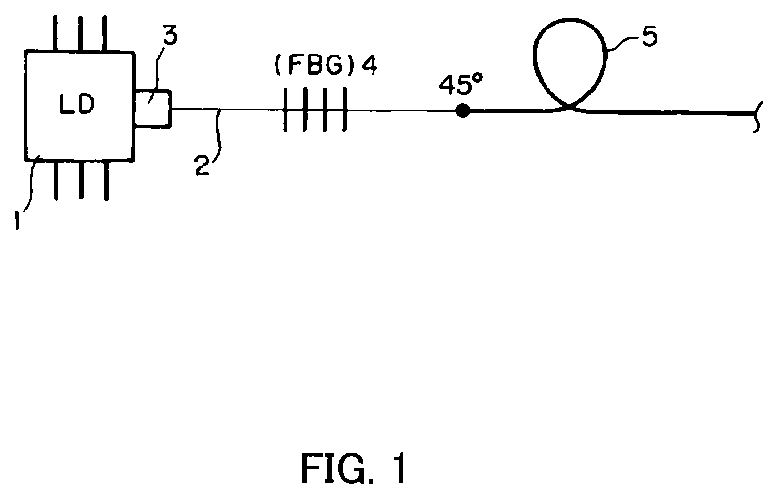
[0079]FIG. 1 shows an embodiment of a depolarized laser diode module which utilizes a polarization maintaining fiber as a depolarizer. The depolarized laser diode module includes: a laser diode module which has a laser diode 1 and a polarization maintaining fiber 2 arranged at the output side thereof; and a depolarizer which utilizes a polarization maintaining fiber for depolarization 5. The laser diode 1 and the polarization maintaining fiber 2 are combined by an optical combining part 3. In the polarization maintaining fiber 2, a Fiber Bragg Grating (FBG) 4 is formed.

[0080]This polarization maintaining fiber 2 and the polarization maintaining fiber for depolarization 5 are usually fusion-spliced in such a manner that principal axes thereof form an angle of 45°.

[0081]In this depolarize...


PUM


Abstract

The present invention provides the following designing method: in a laser diode module or a depolarized laser diode module which has one laser diode and one polarization maintaining fiber connected to the output side thereof, the length of the polarization maintaining fiber is a value obtained by calculation of equation 37 with use of a longitudinal mode spacing Δλoutput light from the Fabry Perot (FP) laser diode, an oscillating center wavelength λ0 of the laser light, a beat length LBeat 1 of the polarization maintaining fiber and an optical wavelength λBeat used in the measurement of the LBeat 1. (Equation 37)LPig<λ02Δλ×LBeat⁢⁢1λBeat⁢⁢1

Description

BACKGROUND OF THE INVENTION[0001]1. Field of the Invention[0002]The present invention relates to a method for designing the length of a polarization maintaining fiber provided at the output side of a laser diode module for outputting laser light to be depolarized, a method for designing the length of a depolarizer, a laser diode module and a depolarized laser diode module manufactured based on the design method, and an optical amplifier which utilizes such a laser diode module as a pump light source.[0003]2. Related Art[0004]An optical amplifier for amplifying signal light in an optical fiber by utilizing as pumping means laser light from a semiconductor laser device (laser diode: LD) plays an important role in a optical communication system. Among such optical amplifiers, an optical fiber Raman amplifier, which utilizes a Stimulated Raman Scattering in an optical fiber, has outstanding noise performance. Therefore, an optical fiber Raman amplifier has become indispensable for optic...

Claims


Application Information

Patent Timeline
Patent Type & Authority Patents(United States)
IPC IPC(8): H01S3/13H01S3/30H01S5/14
CPCH01S5/146H01S3/094003H01S5/06236H01S3/302H01S3/094073
Inventor MATSUSHITA, SHUNICHINAMIKI, SHUEMORI, YOSHIHIRO
Owner FURUKAWA ELECTRIC CO LTD
Why Eureka
Try Eureka