Receiving device and repeating device
a technology of receiving device and repeating device, which is applied in the direction of special services for subscribers, broadcast service distribution, instruments, etc., can solve the problems of increasing communication costs and cumbersome access operation, and achieve the effect of reducing user labor and lowering communication costs
- Summary
- Abstract
- Description
- Claims
- Application Information
AI Technical Summary
Benefits of technology
Problems solved by technology
Method used
Image

Examples
first embodiment
[1] First Embodiment
[0040][1.1] Configuration of First Embodiment
[0041](1) Configuration of Entire System
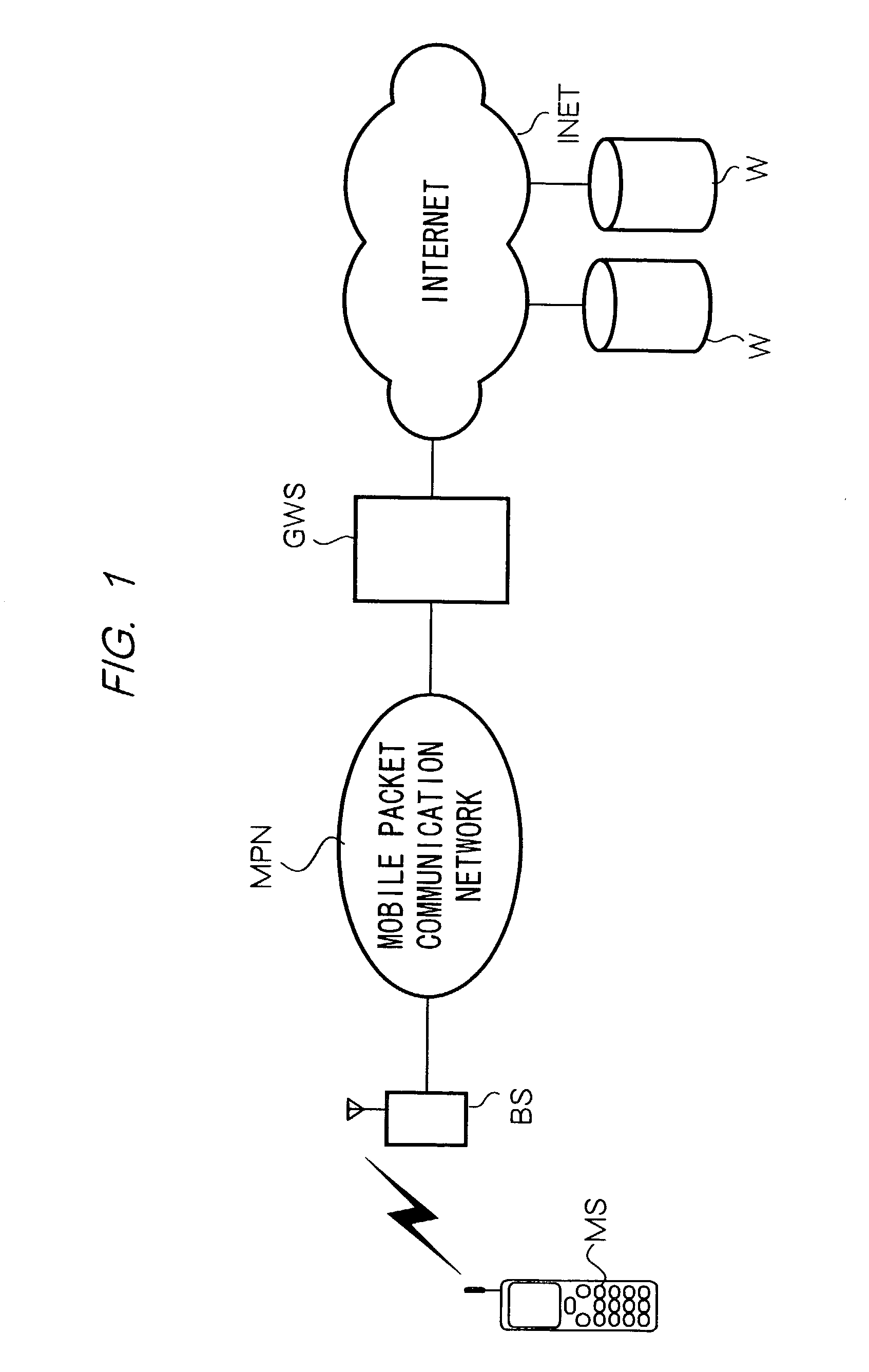
[0042]FIG. 1 is a block diagram showing a configuration of a mobile communication system according to the first embodiment. As shown in FIG. 1, the mobile communication system comprises a plurality of mobile stations MS; a mobile packet communication network MPN; a base station BS served by mobile packet communication network MPN; a gateway server GWS; Internet INET; and a plurality of IP servers W. For simplicity, FIG. 1 illustrates one mobile station MS and one IP server W out of a plurality of mobile stations MS and IP servers W, served by the mobile communication system.
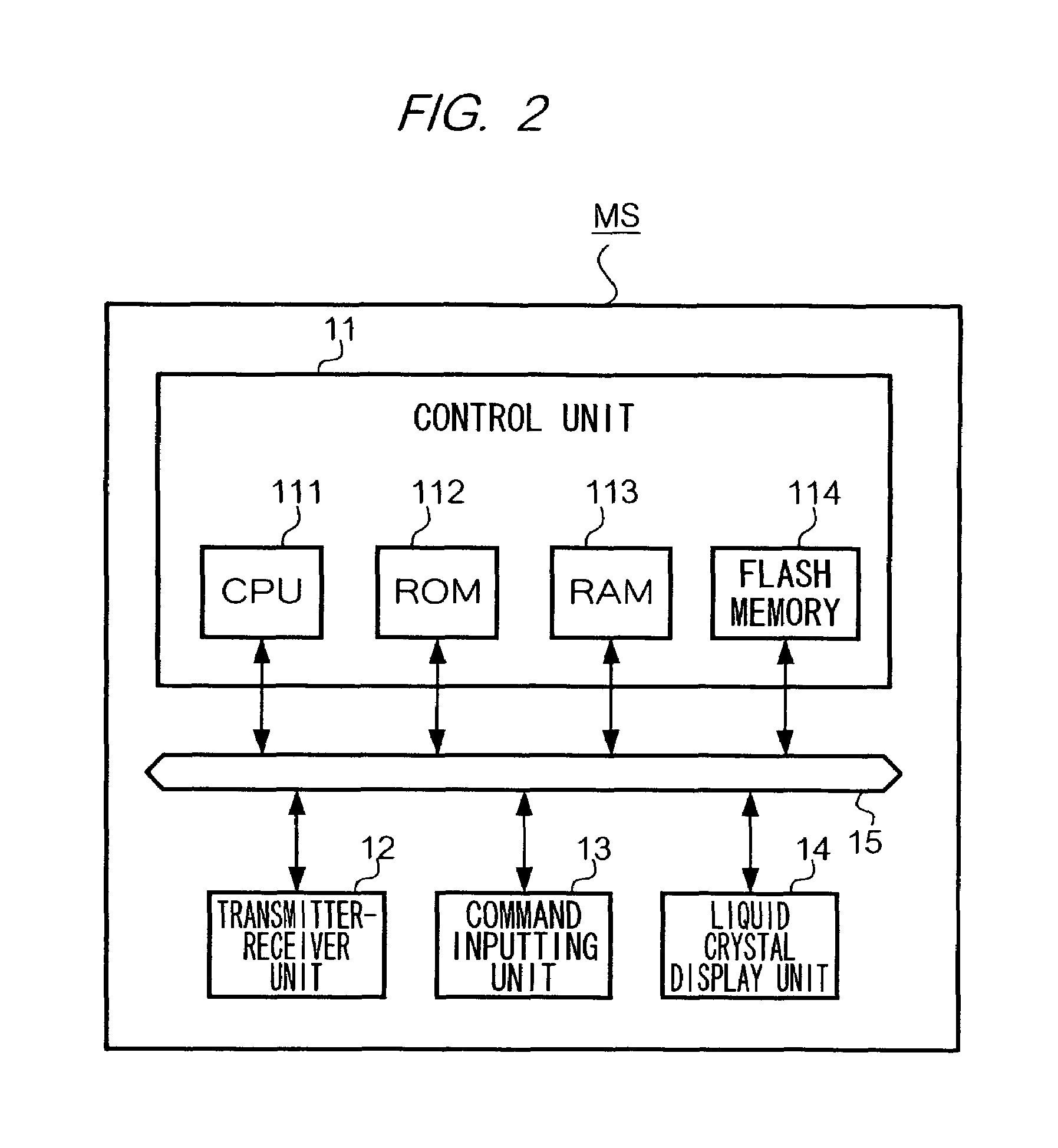
[0043]A mobile station MS performs packet communications through the mobile packet communication network MPN shown in the drawing and performs voice communications through a mobile telephone network not shown. To carry out these functionalities, the mobile station MS comprises a voice input / output unit for ena...
second embodiment
[2] Second Embodiment
[0083][2.1] Configuration of Second Embodiment
[0084]The configuration of the mobile communication system according to the second embodiment is similar to the one shown in FIG. 1. Thus, unless otherwise specified, the components of the configuration according to the second embodiment are shared by the first embodiment and perform the same operations as those of the first embodiment.
[0085]In the second embodiment, the flash memory 114 of the mobile station MS stores an address management table TBL3 instead of the aforementioned access destination storing table TBL1 and link destination storing tables TBL2.
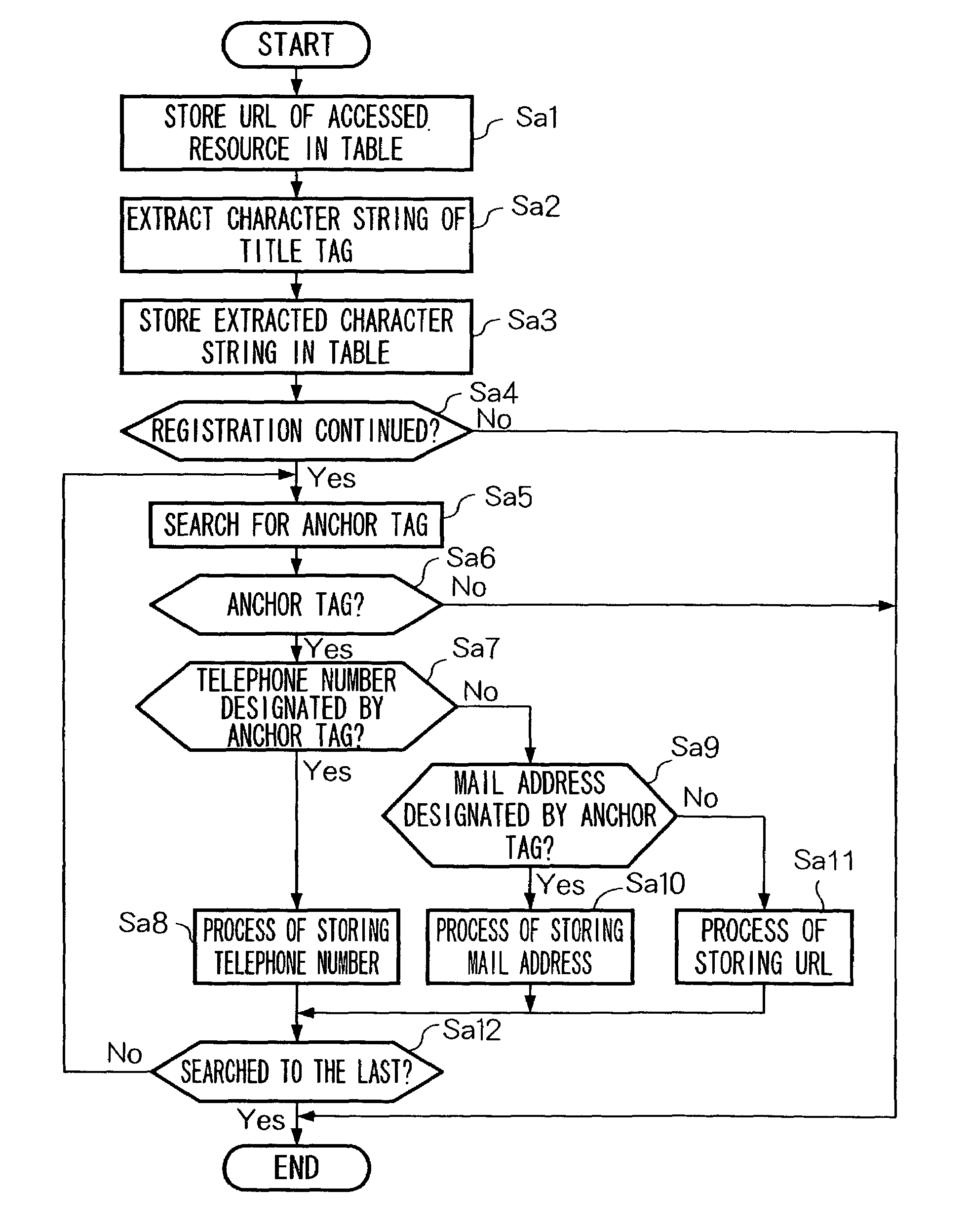
[0086]FIG. 12 is a diagram showing the content of an address management table TBL3. The address management table TBL3 stores the URLs of home pages and so on, which the user has actually accessed from the mobile station MS. In relation to each of the stored URLs, the address management table TBL3 also stores title data for the URL and one telephone number and one...
third embodiment
[4] Third Embodiment
[0115]FIG. 17 is a block diagram showing a configuration of a mobile communication system according to the third embodiment. In FIG. 17, the components corresponding to the components of FIG. 1 are assigned the same references numbers as those of FIG. 1.
[0116]In the mobile packet communication system according to the third embodiment, unlike the first embodiment, a mobile station MS2 transmits a request for registering URLs to a gateway server GWS2, and the gateway server GWS2 carries out registering the URLs. Thus, the access destination storing table TBL1 and the link destination storing tables TBL2 are not formed in the flash memory 114 of the mobile station MS2. The gateway server GWS2 performs the same function of relaying communications as the gateway server GWS performs in the first embodiment and performs an additional function of registering URLs according to instructions from the mobile station MS2 as described below.
[0117]The gateway server GWS2 compri...
PUM
 Abstract
Description
Claims
Application Information
 - Generate Ideas
- Intellectual Property
- Life Sciences
- Materials
- Tech Scout
- Unparalleled Data Quality
- Higher Quality Content
- 60% Fewer Hallucinations
Browse by: Latest US Patents, China's latest patents, Technical Efficacy Thesaurus, Application Domain, Technology Topic, Popular Technical Reports.
© 2025 PatSnap. All rights reserved.Legal|Privacy policy|Modern Slavery Act Transparency Statement|Sitemap|About US| Contact US: help@patsnap.com