Transition signal control unit and DMA controller and transition signal control processor using transition signal control unit

a technology of transition signal and control unit, which is applied in the direction of generating/distributing signals, instruments, pulse techniques, etc., can solve the problems of asynchronous transition signaling not being implemented, affecting the popularization of this method, and difficulty in designing a relatively large-scale circuit, etc., and achieves the effect of easy understanding

Inactive Publication Date: 2006-07-04
LAPIS SEMICON CO LTD
View PDF15 Cites 9 Cited by
  • Summary
  • Abstract
  • Description
  • Claims
  • Application Information

AI Technical Summary

Benefits of technology

[0045]It is an object of the present invention to solve the problems of the above mentioned prior art, and to provide a transition signal control unit which can execute asynchronous transition signal control in a ...

Problems solved by technology

. . , which are transition signals, take charge, and as a result, asynchronous transition signaling cannot be implemented.
However, the conventional asynchronous design method described in Document 1, for example, has more disadvantages as explained in the following (a) and (b), than the above mentioned advantages, which hinders the popularization of this method.
(a) If the conventional asynchronous design method is used, the design of relatively large-scale circuit is difficult.
However, with the conventional asynchronous design method,...

Method used


Image

  • Transition signal control unit and DMA controller and transition signal control processor using transition signal control unit
  • Transition signal control unit and DMA controller and transition signal control processor using transition signal control unit
  • Transition signal control unit and DMA controller and transition signal control processor using transition signal control unit

Examples


Embodiment Construction

(Transition Signal Control Circuit)

(1) Configuration

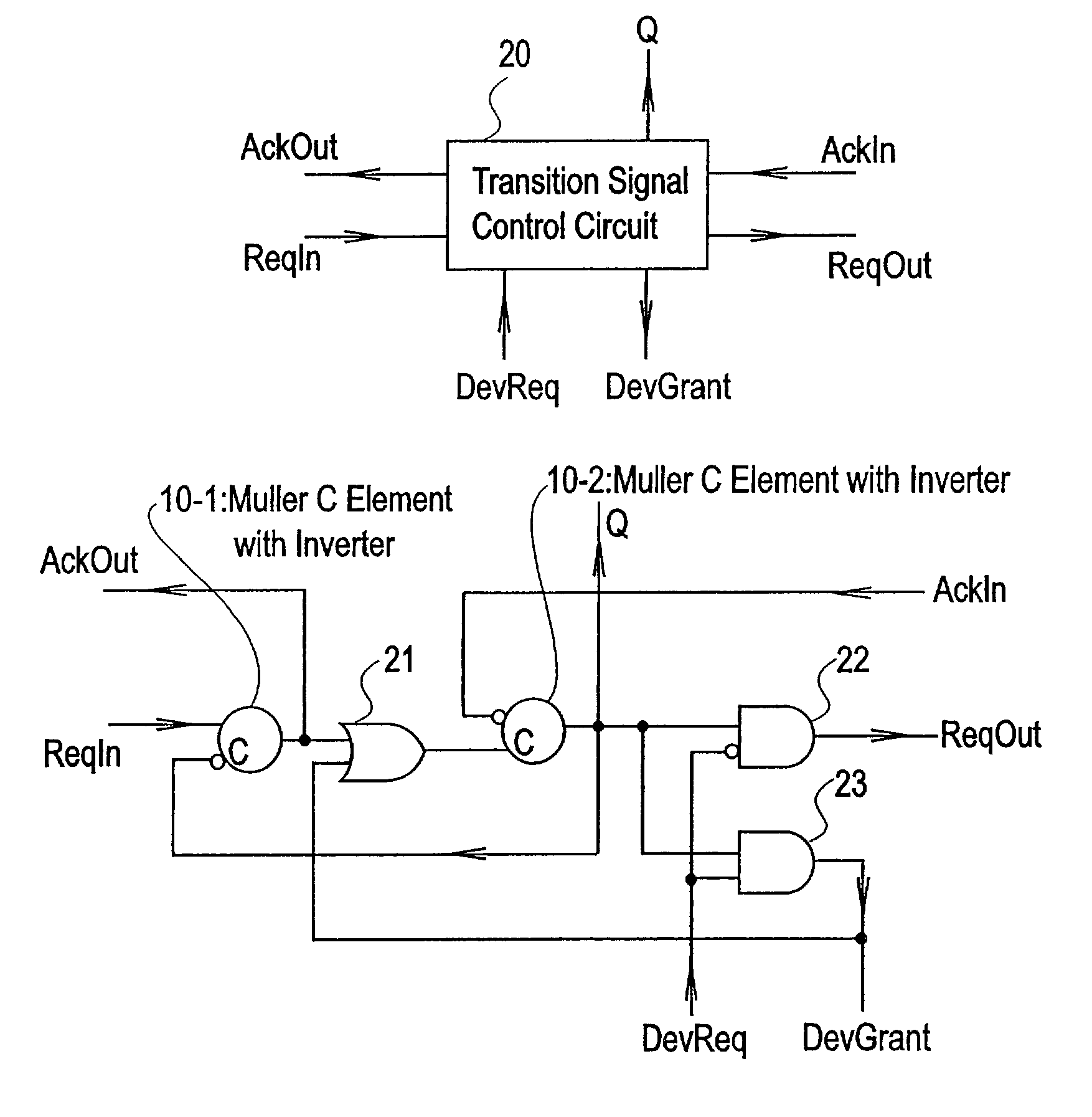
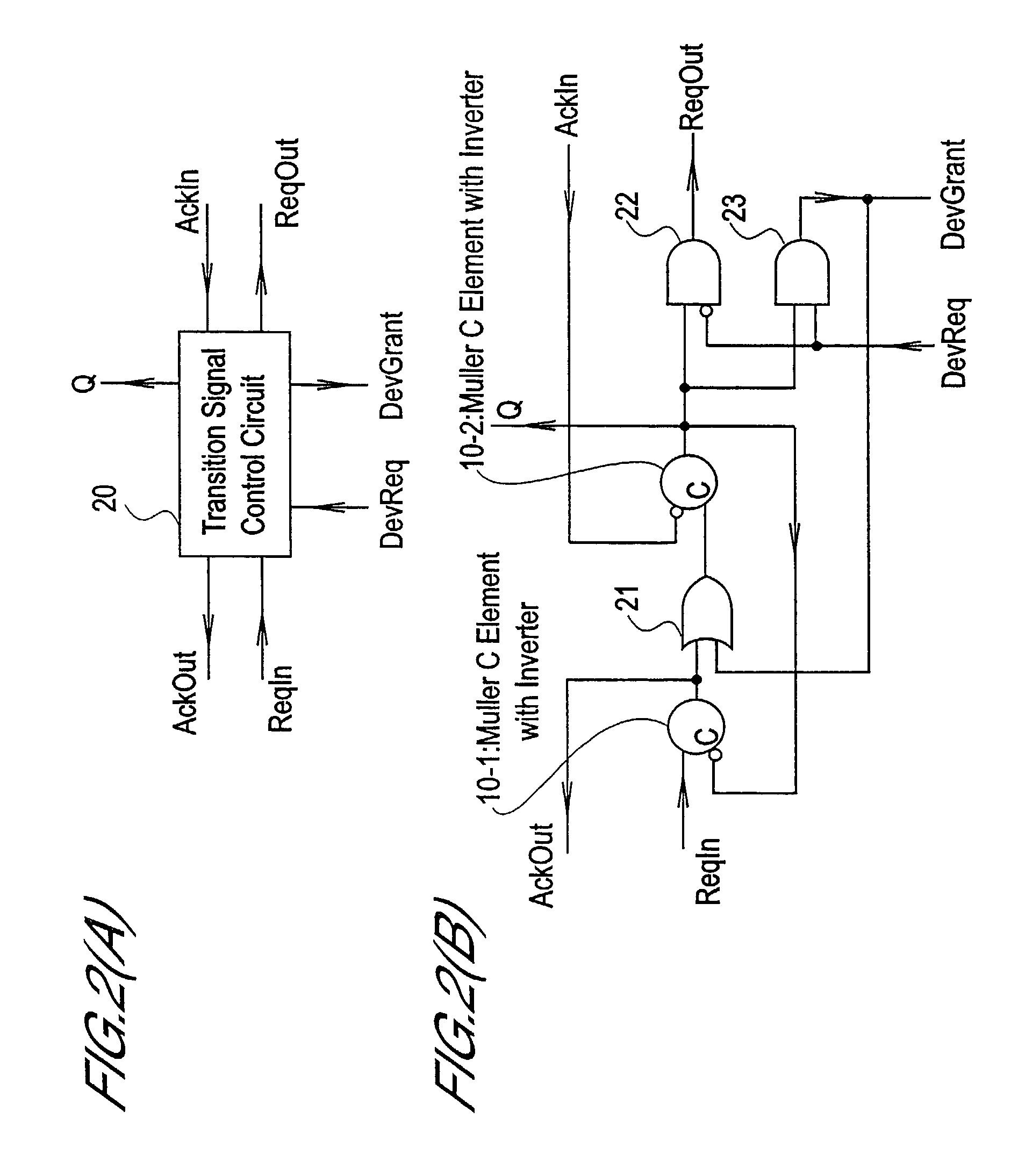
[0081]FIGS. 2(A) and (B) are block diagrams of a transition signal control circuit depicting an embodiment of the present invention, where FIG. 2(A) shows a simplified diagram (symbols), and FIG. 2(B) is a circuit diagram.

[0082]The transition signal control unit according to the present invention comprises a transition signal control circuit where a loop holding a token is created using a plurality of Muller C elements with inverter and gate circuits, wherein the transition signal control circuit uses a device request signal DevReq to be input as a clock signal, and one of the plurality of Muller C elements with inverter included in the transition signal control circuit transfers the token being held to the subsequent circuit according to the input of the device request signal DevReq or device response signal DevGrant.

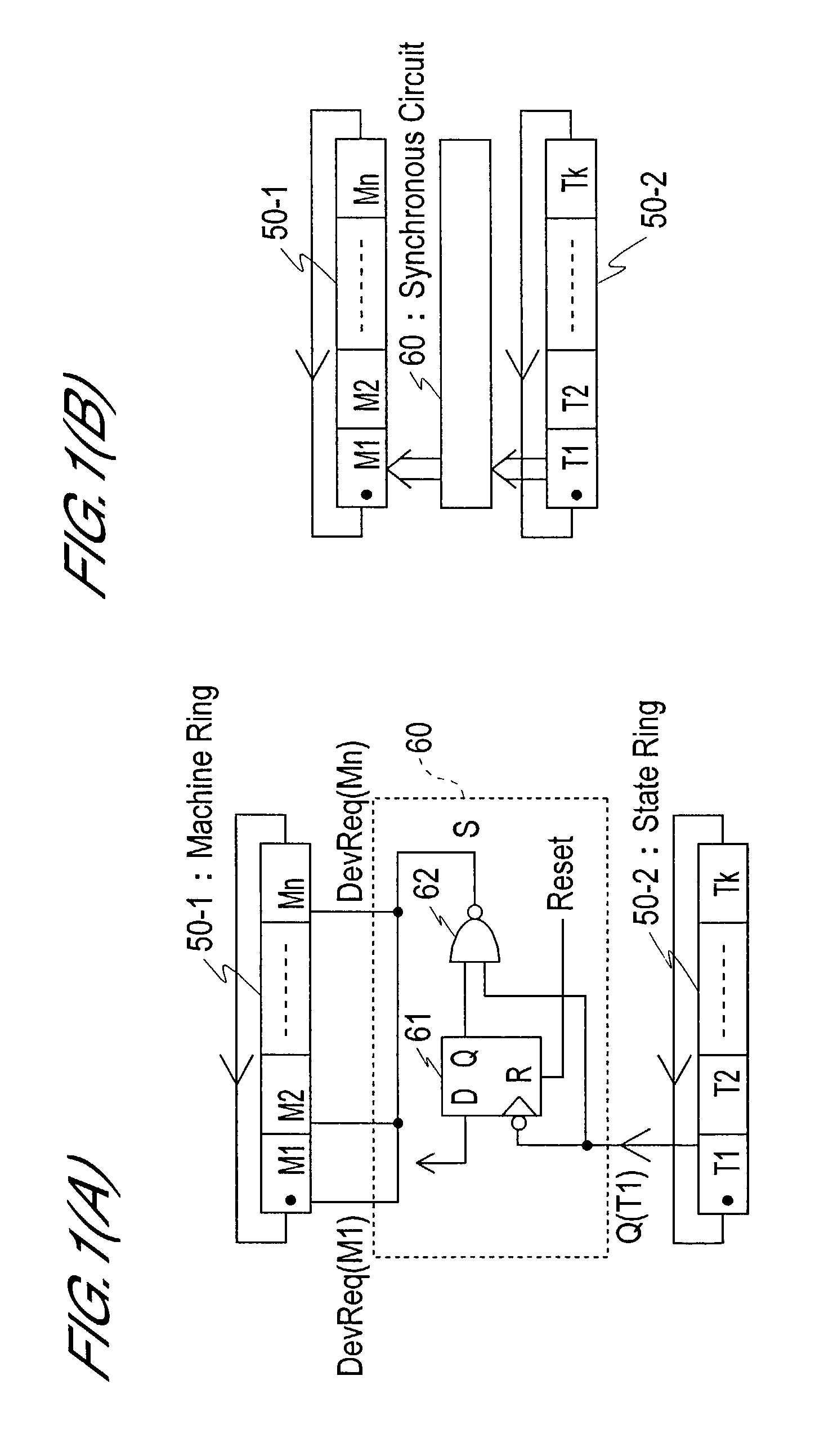
[0083]Such transition signal control circuits when connected to each other can create a control circuit group with ...


PUM


Abstract

Transition signal control for creating asynchronous timing is provided using a transition signal control circuit, which includes Muller C elements each with an inverter. The control device is constituted by a machine ring including n-stages of transition signal control circuits, a state ring including k-stages of transition signal control circuits, and a synchronous circuit for synchronizing with the machine ring by receiving a vector which is output from the state ring. When the output vector of the state ring is received, the synchronous circuit outputs a vector to the machine ring. The output vector of the machine ring and the output vector of the state ring create timings for controlling the processor, for example, asynchronously, and these timings are input to the instruction decoder, for example.

Description

BACKGROUND OF THE INVENTION[0001]1. Field of the Invention[0002]The present invention relates to a transition signal control unit constructed using a ring control circuit, which is created by connecting a plurality of transition signal control circuits comprised of Muller C elements with inverter in a ring shape or in a cascade connection, and a DMA (Direct Memory Access) controller and transition signal control processor which are constructed using this transition signal control unit.[0003]2. Description of Related Art[0004]Prior art related to such a field is, for example, those stated in the following documents.[0005]Document 1: Magazine “bit”, Vol. 22, No. 3, published by Kyoritsu Publishing, pp. 246–268; Paper from Commemorative Lecture on Winning 1998 ACM Turing Prize (Ivan E. Sutherland: Micro-pipelines, CACM, Vol. 32, No. 6, pp. 720–378)[0006]Document 2: Japanese Patent Laid-Open No. 6-90165[0007]Document 3: Japanese Patent Laid-Open No. 6-96019[0008]Document 4: Japanese Pat...

Claims


Application Information

Patent Timeline
IPC IPC(8): G06F1/04G06F13/28G06F13/368H03K19/20H04L12/28
CPCG06F13/28
Inventor HORIE, KIMITOTAKEDA, KOICHI
Owner LAPIS SEMICON CO LTD
Why Eureka
Try Eureka