
Spraying device system and method of dispersing and disseminating materials

Inactive Publication Date: 2006-07-11
RD
View PDF34 Cites 33 Cited by
  • Summary
  • Abstract
  • Description
  • Claims
  • Application Information

AI Technical Summary

Benefits of technology

[0009]The present invention is directed to a spraying system and techniques / methods for the application of liquid materials to targeted portions of the ambient environment, and particularly one for the efficient spraying of selected liquid droplets, such as (without limitation) liquids employing chemical formulations for insect control / eradication, herbicide application, insecticide application, paint application, water application, fertilizer application, antibiotic application and application of cleaning, stripping, and degreasing solutions for household and industrial uses. Although it is contemplated that the present invention has particular application and utility in the field of spraying and disseminating formulations and agents to facilitate mosquito and insect control thereby protecting human populations from diseases and pathogens, such as the West Nile Virus, malaria, and various forms of encephalitis, it should be seen that the present invention may also be utilized to deliver formulations and agents to control mosquitos and various insects among animal and livestock populations, zoos, food production facilities that utilize live animals, and game preserves. Further, the present invention could be utilized to deliver airborne medical products, vaccines, and antidotes to both human and animal populations in response to a specific medical or epidemiological event. The system generally employs a kit or combination of spraying equipment which is lightweight, compact, and requires a relatively low level of maintenance on the part of the entity applying the materials. The system functions through the spraying of accurate and efficient droplets through the combination of fluid and air by means of a low emission engine or other power source and a compressor. It is contemplated that the present invention may further comprise a dual-use feature having functionality as an air compressor with regulated air take-off whereby a plurality of tools or devices could also be powered through the air compressor utilizing various forms of fittings, such as quick disconnect fittings known in the art.
[0010]In a particular preferred embodiment, the efficient liquid droplet size may have fixed or variable flow capabilities, which can be gravity or siphoned fed, and facilitated through the use of at least one nozzle (single or multiple). The nozzle utilized in the present invention may be fed by gravity, siphon, pressure feed, or other pressure fed internal or external mix design. For instance, the present invention may utilize a Venturi-type nozzle, a high-pressure nozzle, hydraulic nozzle, siphon or gravity fed air assisted nozzle, air atomizing nozzle, blow-off nozzle, ultrasonic nozzle, thermal nozzle applications and technology, and all other forms of atomizing or spray nozzles. Although it is contemplated that a preferred nozzle is a Venturi-type nozzle configuration, it should be seen that the present invention may also comprise any number of liquid pressure fed nozzles, having either an internal or external mix, as well as the use of a pressure fed pump configuration. Generally speaking, air assisted nozzles provide very fine droplets that are smaller in size than traditional nozzles. The nozzle of the present invention may or may not have drip characteristics and / or automatic self-cleaning features to reduce the maintenance and clean-up demand depending upon the selected application or spraying environment. Further, the nozzle design of the present invention may incorporate and utilize a variety of patterns such as flat, full cone, hollow cone, fan, etc.

Problems solved by technology

The system generally employs a kit or combination of spraying equipment which is lightweight, compact, and requires a relatively low level of maintenance on the part of the entity applying the materials.

Method used


Image

  • Spraying device system and method of dispersing and disseminating materials
  • Spraying device system and method of dispersing and disseminating materials
  • Spraying device system and method of dispersing and disseminating materials

Examples


Embodiment Construction

[0031]A number of advantages are realized in accordance with the present invention, including, but not limited to, the ability to deliver and apply a liquid atomized spray to targeted portions of the ambient environment.

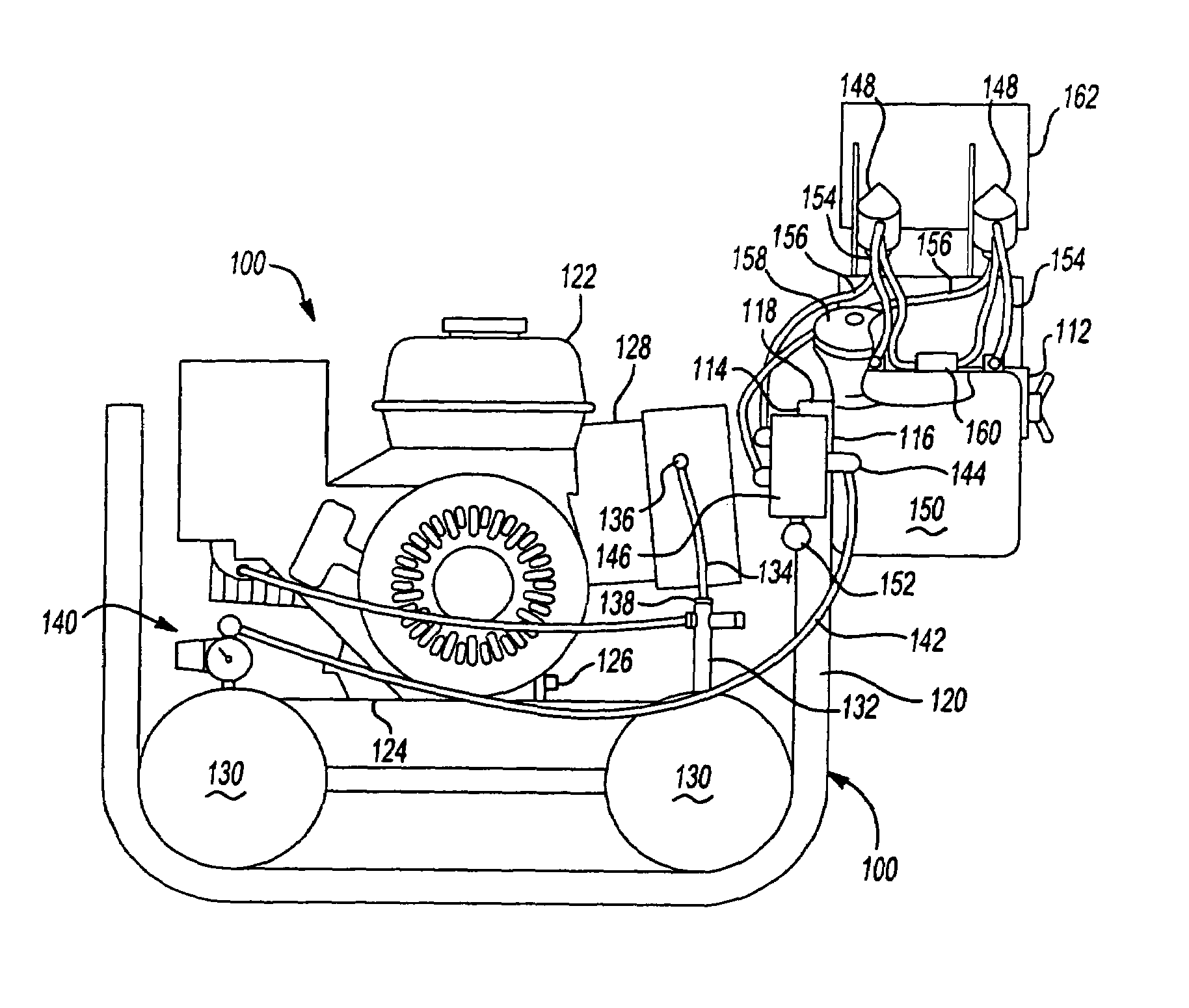
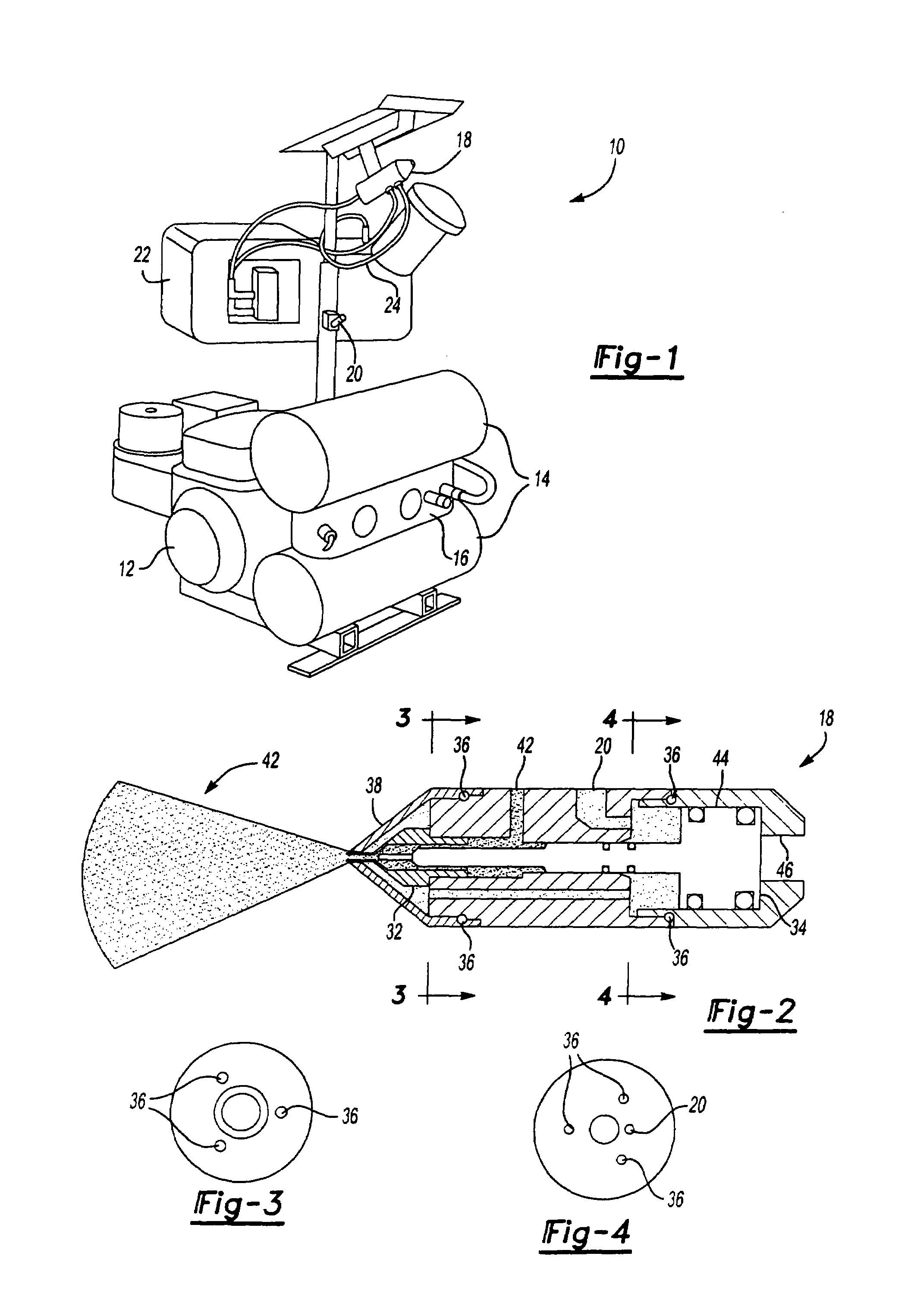
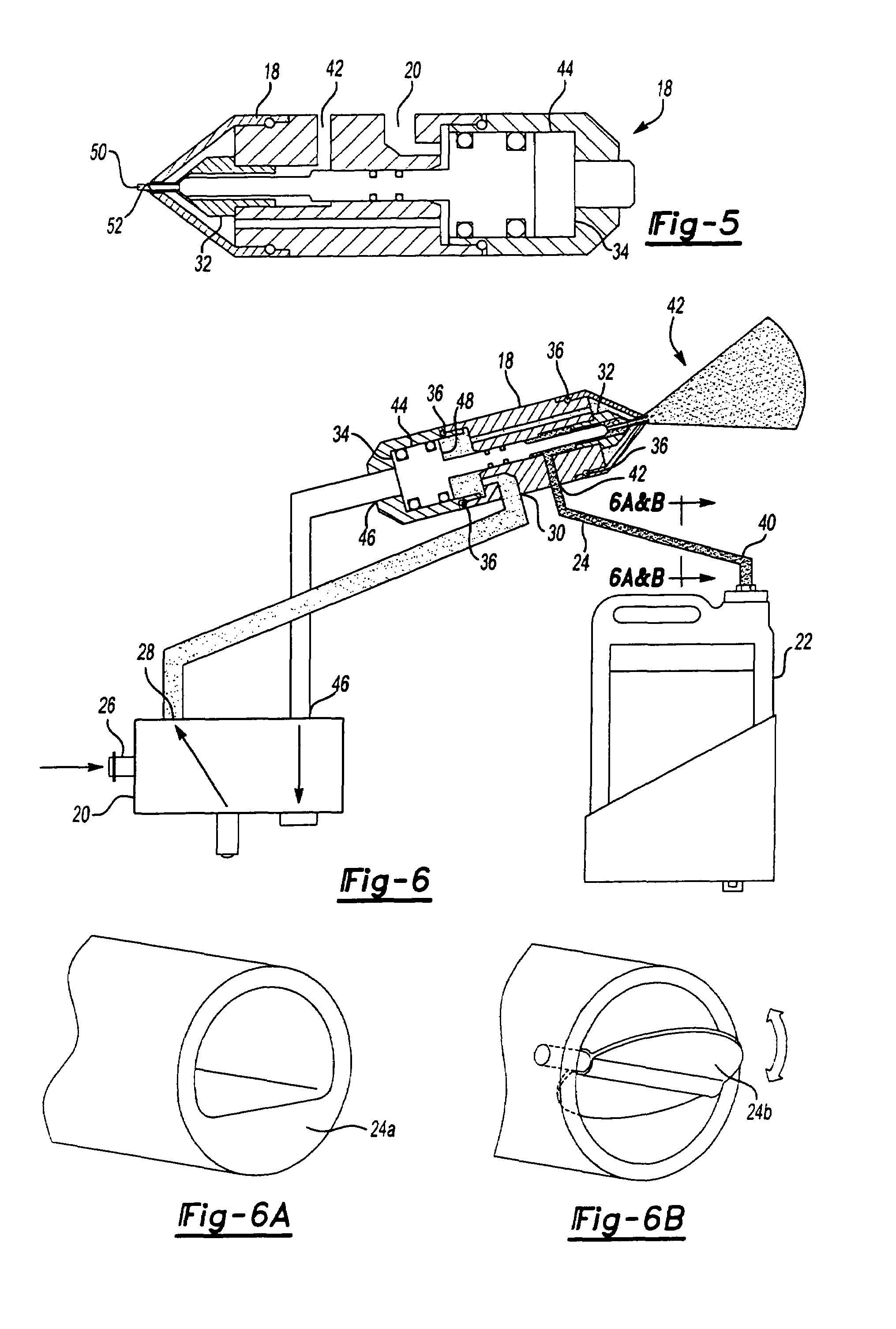
[0032]With reference to FIG. 1, a first preferred embodiment of the present invention is there shown and includes a spraying device 10 able to produce a precise degree of liquid droplet generation on a repeatable basis by combining a specified rate of regulated flow of a liquid material with a targeted and regulated flow of high-pressure air.

[0033]Specifically, the spraying device 10 includes an engine driven direct drive compressor 12 that can be powered by electricity, gasoline, diesel fuel, ethanol, kerosene, hydraulic, air motor, electrical motor, fuel cell technology, or the like. In addition, the engine driven compressor 12 can utilize direct drive, belt drive, chain drive, or gear driven technology known in the art. Coupled to the compressor 12 is at least one...


PUM


Abstract

The invention includes a spraying device (10) for producing a precise degree of liquid droplet generation on a repeatable basis by combining a specified rate of regulated flow of liquid material with a regulated flow of high-pressure air. The spraying device (10) includes an electric or engine driven direct drive compressor (12). Coupled to the compressor (12) is an air storage tank (14) providing air pulsation reduction to the regulated air and serves as a reservoir for excess airflow generation. A Venturi nozzle (18) is connected to the compressor (12). A liquid supply tube (24) uses a fixed or variable restriction to regulate the liquid flow to the nozzle (18). The vacuum in the liquid supply line (24) draws this liquid flow and mixes the liquid externally with the regulated air in exacting proportions forming specified liquid droplet sizes. The device (10) uses air and liquid regulation combined with a Venturi nozzle (18) and is able to generate extremely consistent liquid droplet sizes.

Description

RELATED CASES[0001]The present application is a divisional of U.S. patent application Ser. No. 10 / 318,927, filed on Dec. 13, 2002 now U.S. Pat. No. 6,805,307, which is also claims the benefit of Provisional Application No. 60 / 341,326, filed Dec. 13, 2001 and is incorporated herein by reference.TECHNICAL FIELD[0002]The present invention relates generally to an improved device, system, and method for the spraying and application of liquids and / or liquid-gas mixtures for a number of purposes such as: insect control / eradication, pesticide applications, medicinal or medical product spraying applications, including spraying antibiotics among livestock, chickens, pigs, etc. and antidotes for potential terrorist activities, herbicide applications, insecticide applications, paint applications, misting applications, cooling applications, water applications, fertilizer applications, horticultural applications, solid-stream applications, and application of cleaning / stripping / degreasing solution...

Claims


Application Information

Patent Timeline
IPC IPC(8): A62C31/00A62C5/00B05B7/04F23D11/36F23D11/40A62C5/02B05B1/30B05B7/06B05B7/12B05B7/24B05B15/02
CPCB05B7/0416B05B7/066B05B15/0233B05B7/1281B05B7/2491B05B7/2494B05B7/1254B05B1/3046A62C5/02B05B1/306B05B15/5225
Inventor DORENDORF, BRUCERIPLEY, VERYLN
Owner RD
Learn More