Apparatus and methods for electrospray applications

a technology of electrospray and apparatus, applied in the direction of particle separator tube details, dispersed particle separation, separation process, etc., can solve the problems of less effective coating, more erratic spray, and more expensive spray tip, so as to facilitate the connection of tubing, minimize the dead volume, and easy maintenance

Active Publication Date: 2006-07-11
UPCHURCH SCI
View PDF5 Cites 35 Cited by
  • Summary
  • Abstract
  • Description
  • Claims
  • Application Information

AI Technical Summary

Benefits of technology

[0015]It is another object of the invention to provide an assembly which allows an operator to easily connect tubing from a first system to tubing for providing an electrospray and providing an electric charge to the fluid.
[0016]It is another object of the invention to provide an assembly for introducing an electric voltage to a fluid for electrospray applications which can be easily maintained.
[0017]It is still another object of the invention to provide an assembly for introducing an electric voltage to a fluid for electrospray applications which minimizes the dead volume, if any, introduced in the system.

Problems solved by technology

One problem with this approach is the gradual ablation of the coating material through coronal discharge, such that the coating becomes less effective and the spray may become more erratic.
A coated spray tip is also more expensive than one that is not coated with a conductive material.
Such nanospray applications require that voltage be introduced into an effluent stream, which is complicated by the fact that microfluidic applications used a closed system for fluid delivery that is of the smallest practical internal volume.
The point at which the voltage source is applied to the effluent stream is commonly referred to as the “liquid junction.” In addition, the reduced size of such samples is typically one or more orders of magnitude from more traditional electrospray applications, thus making it more difficult to provide accurate and precise apparatus which is not overly delicate and subject to breaking.
This additional component increases the internal volume of the system, thereby degrading the performance of the analysis.
Furthermore, the suspended wire in such conventional applications often introduces turbulence into the fluid flow, and thereby interferes with the direct, laminar flow of the effluent, causing undesirable delay.
Maintenance of such a conventional liquid junction often includes the replacement of the entire component or junction when it becomes clogged or when the conductive wire degrades to the point of inefficacy.
This replacement usually involves disassembly of fittings and tubing, and thus can require a significant amount of labor and time.
Such conventional approaches typically involve a number of difficulties.
Fracturing a tube obviously weakens it and locating a fracture close enough to the needle and the wire to introduce a charge to the stream can require significant effort and delays.
Conventional approaches using a T-shaped junction often involve undesirable dead volumes in the system, and can still require significant amounts of time for maintenance and replacement.
Still other difficulties arise from the locations of the wires or electrodes used to apply the voltage to the stream in such conventional applications.
It is undesirable to have exposed wires which can pose safety hazards or allow arcing.

Method used


Image

  • Apparatus and methods for electrospray applications
  • Apparatus and methods for electrospray applications
  • Apparatus and methods for electrospray applications

Examples


Embodiment Construction

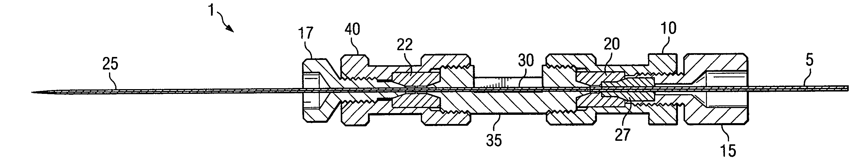
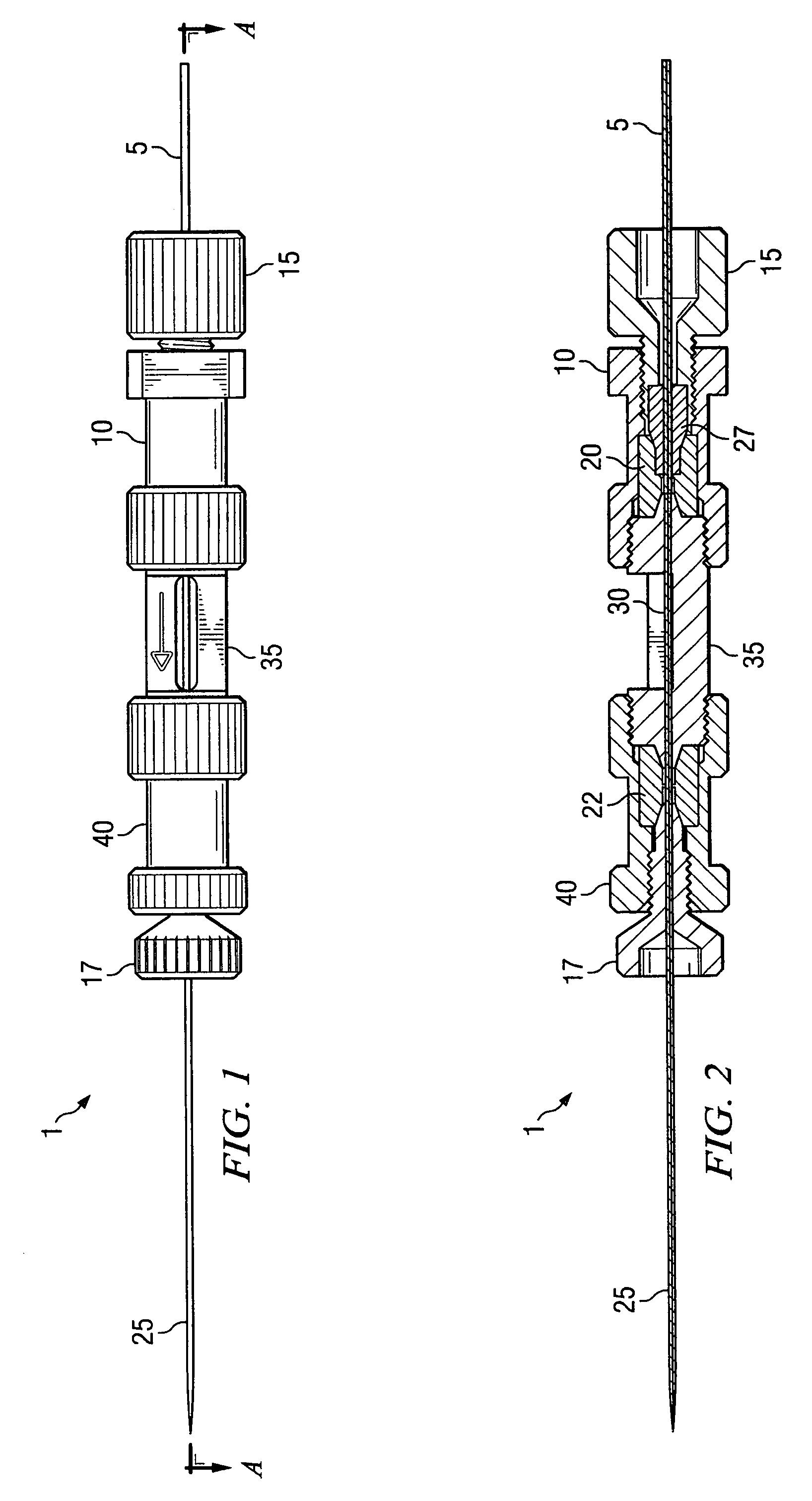
[0030]A conductive union assembly 1 as shown, for example, in FIG. 1, provides a novel solution by creating a non-invasive method to apply voltage to a flowing stream. This conductive union assembly 1 has a significantly smaller internal volume that a conventional liquid junction and does not introduce the turbulence caused by suspending a wire in the fluid stream as in conventional liquid junctions. Voltage may be applied to the conductive holder 40 in the assembly 1 by various means, which in turn transmits the voltage to the fluid flowing through the assembly 1. The conductive union 22 is easily replaceable in comparison with traditional methods and does not require the use of threaded fittings to hold a voltage wire. This method of applying voltage using a conductive union 22 allows the assembly 1 to adapt readily to diverse fluid delivery systems. Furthermore, a column can be connected directly to the fluid system via the conductive union assembly 1. This direct connection prod...


PUM


Abstract

A device and methods are provided, the device comprising a conductive union disposed in a conductive holder, a first fitting capable of coupling with the holder and fluidly communicating with the conductive union, and a spray tip disposed in the fitting and communicating with the conductive union along an axis. The device also comprises a ferrule and fitting capable of coupling with a second holder and communicating with a second conductive union, a tube disposed in the ferrule and fluidly communicating with the first conductive union and the spray tip along the axis. The assembly also includes an insulating member removably secured to the first and second conductive unions to electrically insulate them when they are electrically connected to first and second voltage levels, respectively.

Description

CLAIM OF PRIORITY[0001]This application claims priority to U.S. Provisional Patent Application Ser. No. 60 / 474,007, filed May 29, 2003, which is hereby incorporated herein by reference.FIELD OF THE INVENTION[0002]This invention relates to apparatus and methods regarding their use that are useful in electrospray applications and other techniques used in analytical systems and methods, such as liquid chromatography and mass spectrometry. More specifically, the invention relates to a conductive junction assembly useful in applying a voltage to a liquid stream for electrospray applications.BACKGROUND OF THE INVENTION[0003]Electrospray techniques may be used for analysis of sample solutions in applications and systems, such as liquid chromatography (LC) and mass spectrometry (MS). In such techniques, a sample solution (such as the effluent from a LC system) may be atomized by an electrospray device and then analyzed with a mass spectrometer. Such techniques are also often used for analys...

Claims


Application Information

Patent Timeline
Patent Type & Authority Patents(United States)
IPC IPC(8): H01J49/00B01DH01J49/04
CPCH01J49/165
Inventor BAILEY, MICHAEL L.LINI, THOMAS J.
Owner UPCHURCH SCI
Why Eureka
Try Eureka