System and method for orthogonal frequency division multiplexed optical communication

a technology of orthogonal frequency division and optical communication, applied in the field of optical communication systems, can solve the problems of increasing the data modulation rate, increasing the number of channels per fiber, and increasing the cost of semiconductor technology and other issues, to achieve the effect of reducing the cost of optical communication receivers and eliminating artificial signals

Inactive Publication Date: 2006-07-11
CELIGHT
View PDF9 Cites 60 Cited by
  • Summary
  • Abstract
  • Description
  • Claims
  • Application Information

AI Technical Summary

Benefits of technology

[0021]Instead of a PMD compensator device, the receiver's PMD compensation control module may provide for a fully digitally-implemented (“all-digital”) polarization compensation. In such an embodiment, polarization compensation is done entirely digitally without the use of an optical polarization compensator device. The matrix components comprising the rotation transformation are updated in parallel to the signal processing of the received symbols thereby eliminating artificial degradations to the signals caused by the PCM's search for the optimum rotation. The optimum rotation is determined by a gradient search based on criteria matched to the data format. The digital PCM eliminates the need for an optical polarization compensator thereby significantly reducing the cost of the optical communication receiver. A metric, such as an envelope stability metric, may be used to help determine the optimum pair of rotation angles for the rotation transformation.

Problems solved by technology

Increasing the data modulation rate is limited by semiconductor technology and cost, as well as frequency-dependent fiber impairments as chromatic and Polarization Mode Dispersion (PMD).
Increasing the number of channels per fiber is limited by the properties of optical component materials.
The loss of circular symmetry results in the difference in the group velocities associated with the two polarization modes of the fiber.

Method used


Image

  • System and method for orthogonal frequency division multiplexed optical communication
  • System and method for orthogonal frequency division multiplexed optical communication
  • System and method for orthogonal frequency division multiplexed optical communication

Examples


second embodiment

[0056]FIG. 3b is a block diagram of a transmitter 1400. The transmitter 1400 employs a single light source 1402 that puts out a plurality of evenly spaced-apart spectral lines, separated by some frequency spacing Δf. Preferably, the single light source 1402 puts out K such spectral lines, each being used as a subchannel light beam 332. This allows one to employ a single light source 1402 to provide the illuminating beam. The evenly spaced-apart spectral lines in the frequency domain, may be regarded as the teeth of a “comb”, and so such a light source may be referred to as a ‘comb generator’. U.S. Pat. No. 4,096,448 to Hayes and U.S. Pat. No. 5,347,525 to Fans, whose contents are incorporated to the extent necessary to understand the present invention, exemplify systems for creating optical signals having evenly spaced-apart frequencies.

[0057]In the transmitter 1402 of FIG. 3b, the comb generator 1402 preferably includes circuitry to ensure even frequency spacing between the teeth. ...

first embodiment

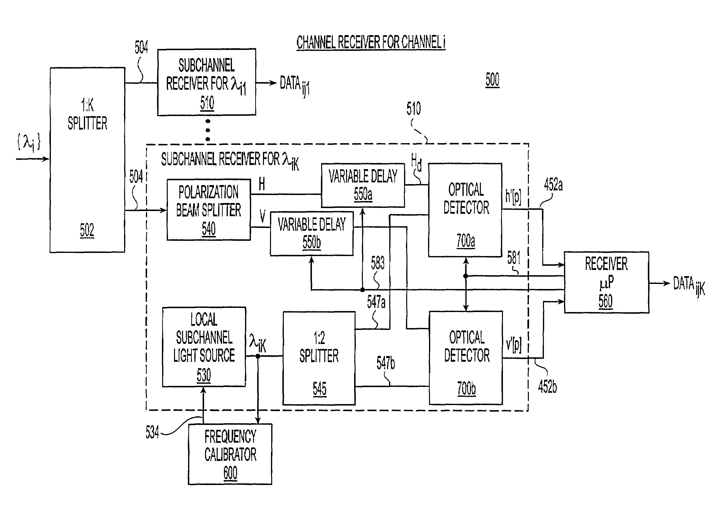
[0065]FIG. 5a is a block diagram of a channel receiver 500, of the sort that can be used as the receiver 260 in FIGS. 2a &2b. The nomenclature used to describe receiver 500 corresponds to a receiver for channel i.

[0066]The channel signal {λi} from the DWDM demultiplexer 230, which carries K subchannel signals each having a data stream with both H and V components, is directed into a 1:K receiver splitter 502 that splits the optical channel signal into K identical receiver channel signals 504. Each of the identical receiver channel signals 504 is input to one of K subchannel receivers 510, each subchannel receiver 510 being configured to detect one subchannel {λik}. For purposes of clarity, only one subchannel receiver 510 is shown in detail in FIG. 5a.

[0067]The receiver channel signal 504 is first directed into a polarization beam splitter 540 which splits the incoming signal into two orthogonal components, designated ‘H’ and ‘V’. The H- and V-components are subjected to variable d...

third embodiment

[0108]FIG. 11c presents a self-homodyne receiver 1100c having self-homodyne sub-channel receivers 110c. This self-homodyne embodiment has a multiple PMD compensators and multiple polarization beam splitters. In self-homodyne sub-channel receiver 1110c, The sub-channel signal 1104 is first input to a 1:2 splitter 1142 to produce two identical sub-channel signals 1104a, one of which is delayed by a one-symbol delay 1144 to produce delayed sub-channel signal 1105a.

[0109]The sub-channel signal 1104a and the delayed sub-channel signal 1105a are input to a 90° optical hybrid circuit 1200 which outputs the four combined signals 731, 735, 733 and 737. The 90° optical hybrid circuit 1200 found in sub-channel receiver 1110c does not have to be polarization sensitive, since it does not receive the polarization beam-split signals. However, it would not hurt to use a polarization-sensitive 90° optical hybrid circuit. The four combined signals 731, 733, 735 and 737 represent the four complex cr...


PUM


Abstract

A system for optical communication send optical signals over a plurality of wavelength channels. Each wavelength channel comprises a number of orthogonal subchannel frequencies which are spaced apart from one another by a predetermined amount. Each of the subchannel frequencies is modulated with data from a data stream. The data modulation scheme splits a subchannel frequency code into H and V components, and further processes the components prior to modulation with data. The various data-modulated subchannels are then combined into a single channel for transmission. The received signals are detected and demodulated with the help of a symbol timing recovery module which establishes the beginning and end of each symbol. A polarization mode distortion compensation module at the receiver is used to mitigate the effects to polarization more distortion in the fiber.

Description

RELATED APPLICATIONS[0001]The present application is a continuation-in-part of U.S. application Ser. No. 09 / 962,243, filed Sep. 26, 2001, which itself claims priority to U.S. provisional application No. 60 / 234,930, filed Sep. 26, 2000.FIELD OF THE INVENTION[0002]The present invention relates to the field of optical communication systems utilizing modulation techniques to obtain high spectral efficiency.BACKGROUND OF THE INVENTION[0003]Dense wavelength division multiplexing (DWDM) increases the capacity of embedded fiber by assigning incoming optical signals to specific frequencies (wavelength, lambda) within a designated frequency band and then multiplexing the resulting signals out onto one fiber. DWDM combines multiple optical signals so that they can be amplified as a group and transported over a single fiber to increase capacity of the telecommunication network. Each signal carried can be at a different rate (OC-3 / 12 / 24, etc.) and in a different format (SONET, ATM, data, etc.). ...

Claims


Application Information

Patent Timeline
Patent Type & Authority Patents(United States)
IPC IPC(8): H04J14/06H04B10/00H04B10/04H04B10/06H04J4/00H04B10/155H04B10/18H04J13/00H04J14/00H04J14/02
CPCH04B10/2543H04B10/2563H04B10/2572H04B10/506H04B10/508H04J14/005H04B10/505H04J14/02
Inventor SHPANTZER, ISAACMEIMAN, YEHOUDATSEYTLIN, MICHAELRITTERBUSH, OLGASALAMON, AVIVFELDMAN, PETERDEMIR, ALPERKINGET, PETERKRISHNAPURA, NAGENDRAROYCHOWDHURY, JAIJEET
Owner CELIGHT
Why Eureka
Try Eureka