
High flow rate water supply assembly

a high-flow rate, water supply technology, applied in water supply tanks, water supply pipes, service pipes, etc., can solve the problem of cold water initially entering, and achieve the effect of rapid water delivery

Active Publication Date: 2006-07-18
KOHLER CO
View PDF9 Cites 15 Cited by
  • Summary
  • Abstract
  • Description
  • Claims
  • Application Information

AI Technical Summary

Benefits of technology

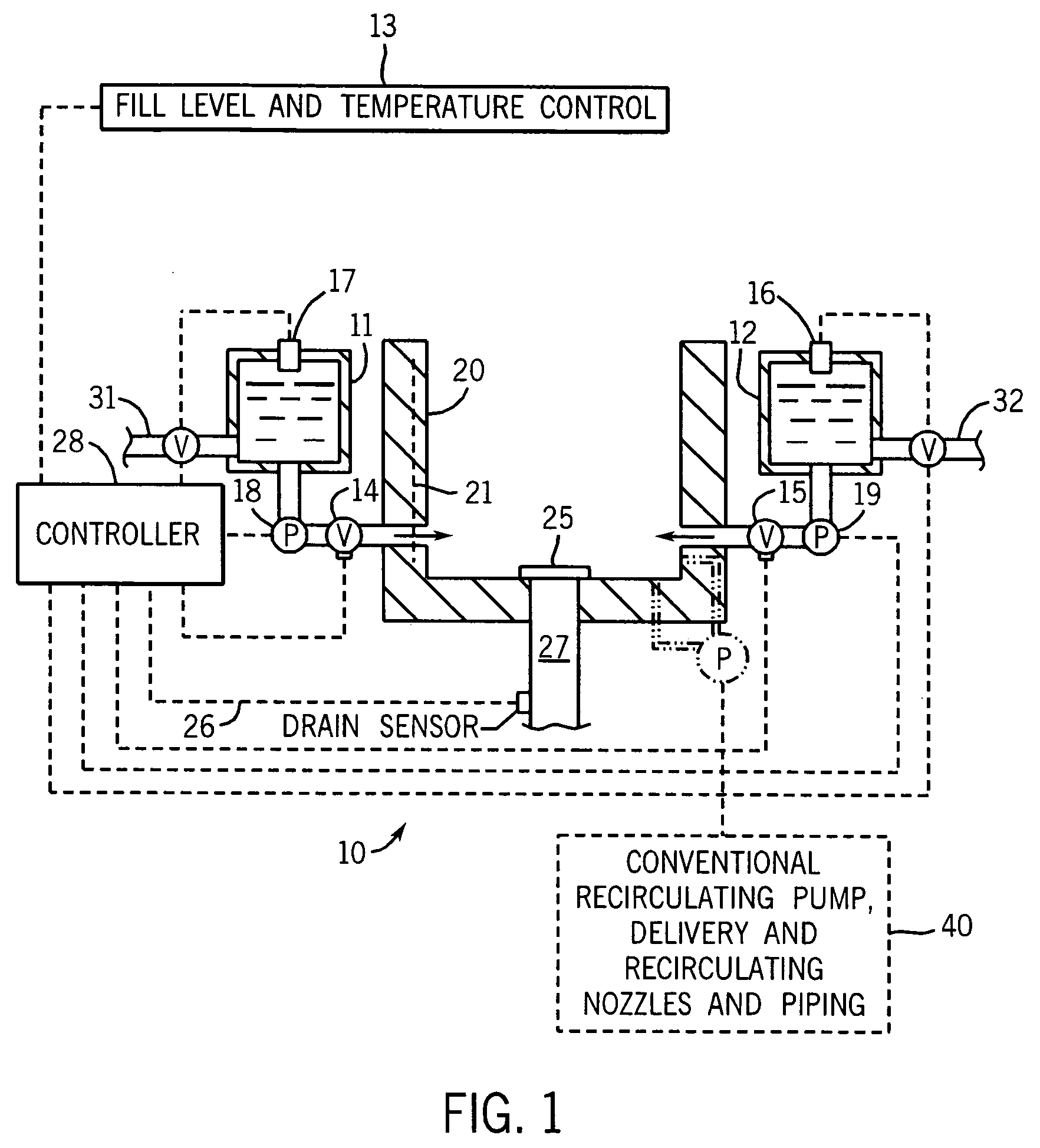
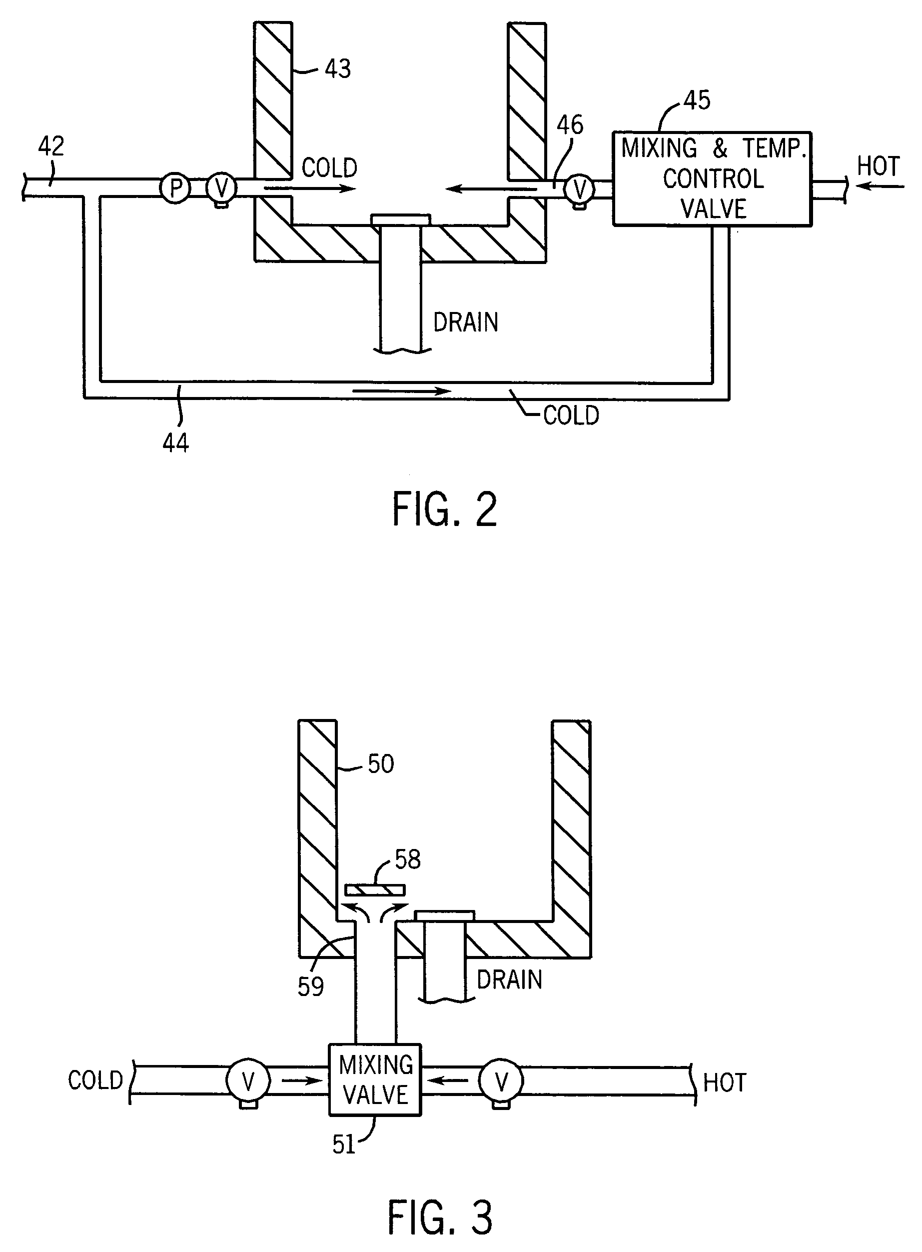
[0016]In a preferred form at least one of the tanks is positioned within twenty (more preferably ten) feet of the basin. This reduces temperature stratification within conduits between the tanks and basin, which can cause the incoming water initially to be colder than desired. Further, it minimizes the amount of special diameter piping that needs to be used when piping diameter is enlarged to achieve the quick “fill”.
[0017]In another preferred form, the delivery means is a centrifugal pressure pump that facilitates a large volume flow rate. Even more preferably, the pump is variable speed, so that splashing can be minimized by providing an initial flow volume delivered at a lower flow rate, for example 10 gallons / minute, and then quickly ramping up to a high flow rate many times the initial rate to rapidly fill the basin.
[0018]In yet another form, there are controls (preferably electronic controls) for monitoring the temperature of water in the basin, for monitoring the height of water in the basin, for initiating refilling of the tanks, for sensing flow from the basin drain, for sensing the presence of non-water objects in the basin, and / or for controlling heating of water in the hot water tank. Among these controls can be those that inhibit resupply of water to at least one of such tanks when the amount (e.g., weight / level / or volume) of water in the basin is in excess of a specified amount. This avoids too much weight being collected at one area of the building, which may be regulated by local ordinances and / or may jeopardize the structural integrity of the room, and / or require special structural bracing.
[0019]The assemblies of the present invention can deliver water from the tanks to such basins at a rate exceeding 75 (preferably exceeding 500, even more preferably exceeding 750) gallons / minute. If the tanks are enclosed, vents are preferably provided to relieve any flow reducing vacuum that may otherwise occur during a basin fill cycle and to alleviate pressure build-up when the tanks are re-filled.
[0025]Accordingly, the invention, in various embodiments, provides assemblies that can much more quickly “fill” large basins in whirlpools, spas, other bathtubs, washing machines, and the like. Further, it can do so without disrupting the water supply of the building in which the system is mounted.

Problems solved by technology

This reduces temperature stratification within conduits between the tanks and basin, which can cause the incoming water initially to be colder than desired.

Method used


Image

  • High flow rate water supply assembly
  • High flow rate water supply assembly
  • High flow rate water supply assembly

Examples


Embodiment Construction

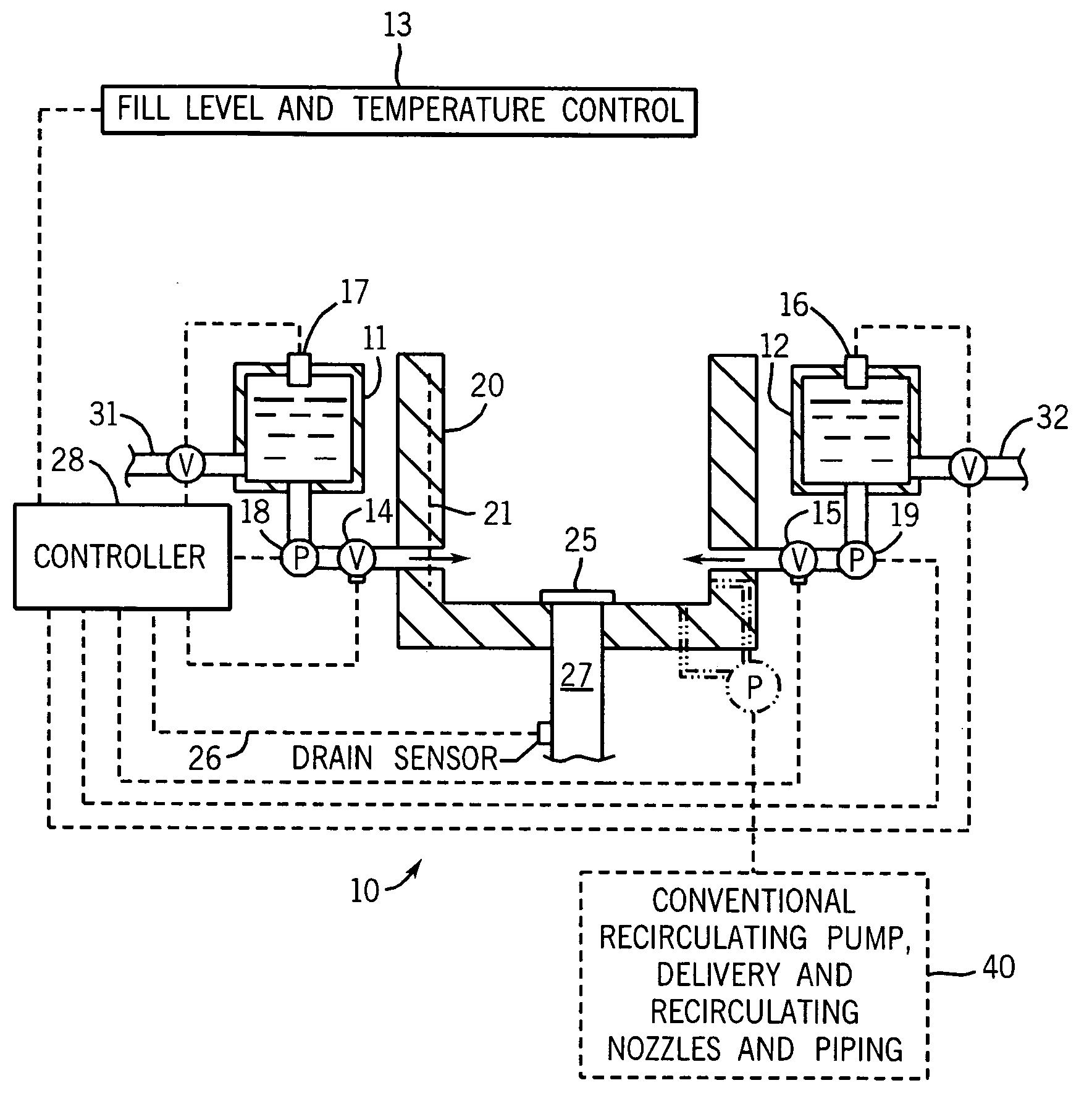
[0034]FIG. 1 depicts a whirlpool tub assembly 10 of the present invention. A cold water storage tank 11 and hot water storage tank 12 are maintained in the full condition between uses. As this system fills the hot water tank from the building hot water heater (not shown), the hot water tank is insulated.

[0035]The water storage tanks can be conventional rigid, such as metal or plastic, vessels. They may also be compliant bladders, or take the form of large cross-sectional area conduit. For the conduit to be considered a tank herein, at least a portion of the conduit must have a passageway of more than 3 square inches (preferably at least about five square inches) in cross-section, which can be circular or otherwise.

[0036]Prior to the fill cycle a sensor (not shown) is read to detect the presence of a person, pet or other non-water object inside the basin. Any suitable sensor for detecting proximity, capacitance, weight or other presence indicating parameter can be used. One possibili...


PUM


Abstract

An assembly for rapidly filing bathtubs, whirlpools, spas, washing machine drums and the like includes a basin, water storage tank(s) (such as hot and cold water storage tanks), and a system for controlling the filling of the basin from the tank(s). When it is desired to supply water to the basin, this is expedited by placing the tank(s) above the basin, using connecting piping with extra large area, using a pressure pump, and / or providing extra large delivery ports. The tank(s) are dedicated to the assembly, and preferably are closely adjacent thereto. Controls are provided to avoid excess weight gathering adjacent the basin.

Description

CROSS-REFERENCE TO RELATED APPLICATION[0001]This application is a CIP claiming priority based on U.S. provisional application 60 / 428,680, filed Nov. 25, 2002.STATEMENT OF FEDERALLY SPONSORED RESEARCH OR DEVELOPMENT[0002]Not applicable.BACKGROUND OF THE INVENTION[0003]The present invention relates to bathtubs, whirlpools, spas, clothes washing machines, and other plumbing devices where a large basin must be supplied with a large volume of water. More particularly, it relates to assemblies for achieving rapid “filling” of such basins.[0004]When it is necessary to fill a large basin with water from a conventional plumbing supply, the filling time can be significant. For conventional bathtubs and whirlpools, the volume of water required for filling is so large that it can take ten minutes or more for a conventional bathtub or whirlpool to fill to a level that satisfies the user. This problem is exasperated in hospitals, and other places of temporary residence like hotels, in which sever...

Claims


Application Information

Patent Timeline
Patent Type & Authority Patents(United States)
IPC IPC(8): A47K3/00A47K3/10A61H33/00D06F39/08E03B7/04E03B11/02E03C1/00
CPCA61H33/0087D06F39/08D06F39/087A61H33/6015E03B7/04E03B11/02E03C1/00D06F39/088Y02A20/00D06F33/42
Inventor OSTROWSKI, MICHAEL H.MUELLER, JEFFREY L.LEWIS, JAMES R.KAYMEN, STANLEY P.SCHOTT, JOHN H.
Owner KOHLER CO
Learn More