Combined intercooler and flame arrester

a technology of intercooler and flame arrester, which is applied in the direction of machines/engines, domestic stoves or ranges, lighting and heating apparatus, etc., can solve the problems of limited cooling achieved by this arrangement, the flame arrester is not well suited for use in most internal combustion engines, and the flame arrester cannot be integrated into the induction system at considerable cost, so as to achieve the effect of minimizing the volume of the surge tank

Active Publication Date: 2006-07-18
BRP ROTAX
View PDF14 Cites 22 Cited by
  • Summary
  • Abstract
  • Description
  • Claims
  • Application Information

AI Technical Summary

Benefits of technology

[0015]The intercooler in accordance with embodiments of the present invention further includes at least one plate extending substantially orthogonal to the longitudinal axis. Each plate includes a central opening therein, which corresponds to the central passageway in the elongated body such that the intake gas is capable of flowing through the central opening. Each plate has a plurality of openings formed thereon about a periphery of the plate. One cooling tube is fed through each opening. A plurality of plates can be spaced along the longitudinal axis of the elongated body. According to a preferred embodiment, with such an arrangement, the diameter of the...

Problems solved by technology

This flame arrester, however, is not well suited for use in most internal combustion engines because of the size constraints associated with most engines.
The flame arrester can only be integrated into an i...

Method used


Image

  • Combined intercooler and flame arrester
  • Combined intercooler and flame arrester
  • Combined intercooler and flame arrester

Examples


Embodiment Construction

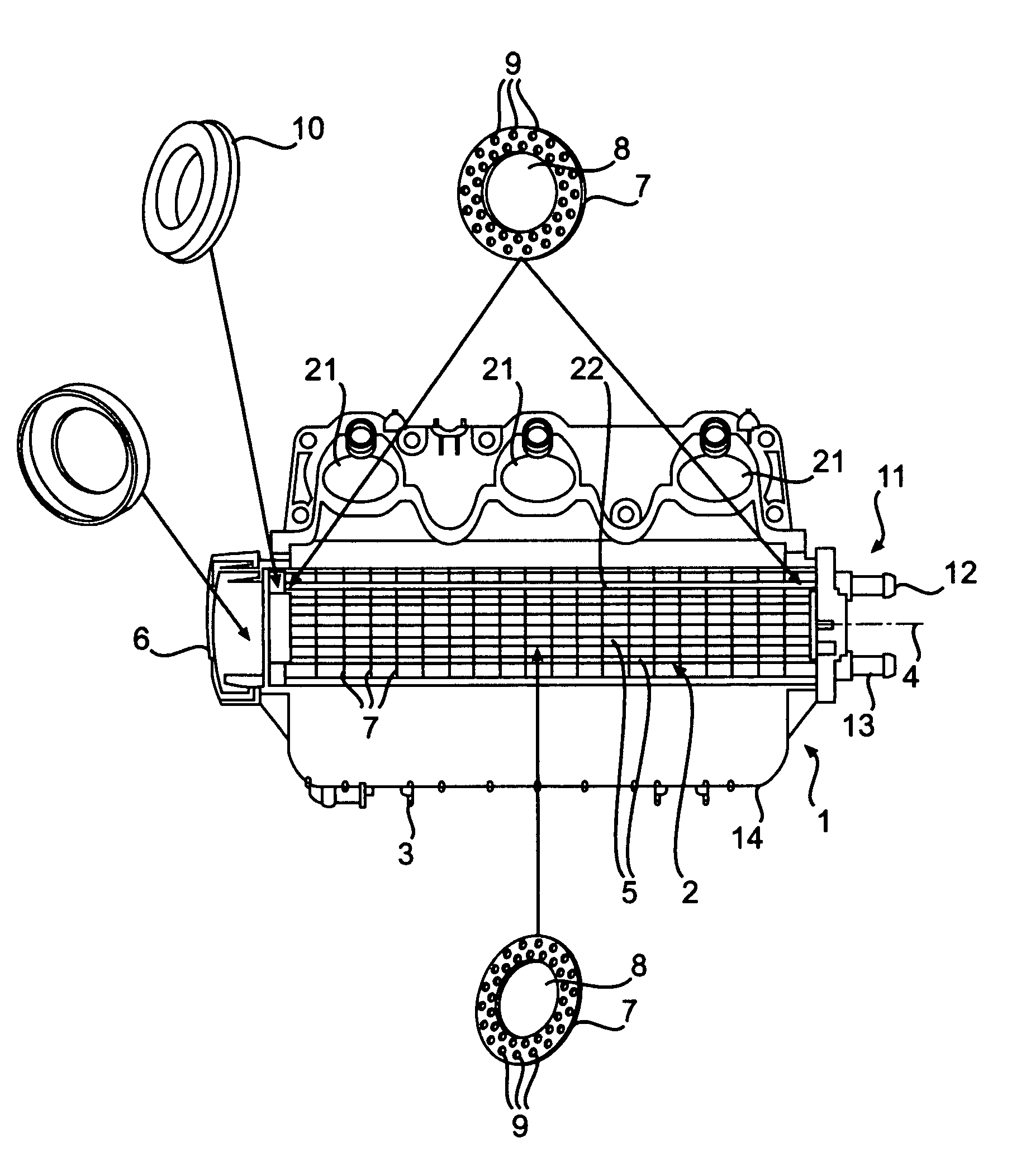
[0030]An internal combustion engine has an air intake system or induction system 1. It is contemplated that the internal combustion engine can be used in personal watercraft, all terrain vehicles, snowmobiles, boats, outboard engines and other vehicles. The induction system 1 is connected to the cylinder head housing (not shown) of the internal combustion engine on a side of the engine opposite an exhaust manifold, as described, for example, in U.S. Pat. No. 6,601,528 to Bilek et al, entitled “Four Stroke Engine With Intake Manifold,” the entire disclosure of which is incorporated herein by reference. The air intake into the engine is effected via an air box, not shown. Air entering the air box can flow through a tube connecting the air box with the engine, and then passes to an air intake manifold or plenum 14, of the induction system 1. The air manifold 14 is preferably formed from a plastic material, however, other materials are contemplated including, metals, high strength alloy...


PUM


Abstract

A combined flame arrester and intercooler for cooling intake gas for an internal combustion engine is disclosed. The intercooler comprises an elongated body having a longitudinal axis. The elongated body has a central passageway that extends substantially parallel to the longitudinal axis. An inlet opening is located on one end of the elongated body such that the intake gas enters the central passageway though the inlet opening. The intercooler further includes a plurality of cooling tubes forming at least a portion of the elongated body. The plurality of tubes substantially surround the central passageway. Each of the cooling tubes is spaced from an adjacent cooling tube such that an air flow path is formed there between. The intake gas is cooled by flowing past the cooling tubes. Preferably, the intake gas flows along the central passageway in the elongated body and radially outward therefrom through the air flow path between the cooling tubes. The intercooler includes at least one plate extending substantially orthogonal to the longitudinal axis. Each plate includes a central opening therein, which corresponds to the central passageway in the elongated body such that the intake gas is capable of flowing through the central opening. Each plate has a plurality of openings formed thereon about a periphery of the plate. One cooling tube is fed through each opening.

Description

CROSS-REFERENCE TO RELATED APPLICATIONS[0001]This application relates to and claims priority to U.S. Provisional Patent Application No. 60 / 433,014, filed on Dec. 13, 2002, the contents of which are incorporated herein by reference.BACKGROUND OF THE INVENTION[0002]1. Field of the Invention[0003]The present invention relates to an internal combustion engine having a flame arrester arranged in an induction system of the engine. In particular, the present invention relates to a flame arrester that is combined with a cooler for the air or mixture of air and gas that is to be drawn into the cylinder or cylinders of the engine.[0004]2. Description of Related Art[0005]According to the prior art, flame arresters are typically arranged in or adjacent the intake port of an internal combustion engine. JP 03054354 A discloses a flame arrester that is incorporated into the induction system of an internal combustion engine so as to prevent the induction system from being damaged by the cylinder ba...

Claims


Application Information

Patent Timeline
IPC IPC(8): F02B33/00F02B29/04F02M35/10F28D7/00
CPCF02B29/0462F02B29/0475Y02T10/146F28D2021/0082Y02T10/12
Inventor BILEK, ANDREASWOLFSGRUBER, ALOISTSCHERNE, RUDOLFPOUILLARD, JEAN-CHARLESSONNLEITNER, MICHAEL
Owner BRP ROTAX
Why Eureka
Try Eureka