Speed differential-dependent hydraulic clutch with a control valve

a technology of hydraulic clutch and control valve, which is applied in the direction of fluid actuated clutches, automatic clutches, non-mechanical actuated clutches, etc., can solve the problems of inaccessible control valves, actuated hydraulically, and not expedient in a genuine control system, and achieves the effect of small diameter

Inactive Publication Date: 2006-07-18
MAGNA STEYR POWERTRAIN
View PDF7 Cites 10 Cited by
  • Summary
  • Abstract
  • Description
  • Claims
  • Application Information

AI Technical Summary

Benefits of technology

[0011]In a first embodiment, the actuator interacts with a selector sleeve which surrounds the second shaft, rotates together with it and can be displaced in the axial direction, and a rod which passes through the selector sleeve and the second shaft and comes into contact with the control element is provided, the second shaft having a slot for the rod to pass through. Since the selector sleeve sits on the shaft, its diameter can be small. The rod permits the movement into the interior of the shaft to be introduced and is guided precisely in the s

Problems solved by technology

This renders the control valve inaccessible to such an extent that it can only be actuated hydraulically.
However, this is not expedient in a genuine control system which is not coupled to the brake system.
As a re

Method used


Image

  • Speed differential-dependent hydraulic clutch with a control valve
  • Speed differential-dependent hydraulic clutch with a control valve
  • Speed differential-dependent hydraulic clutch with a control valve

Examples


Embodiment Construction

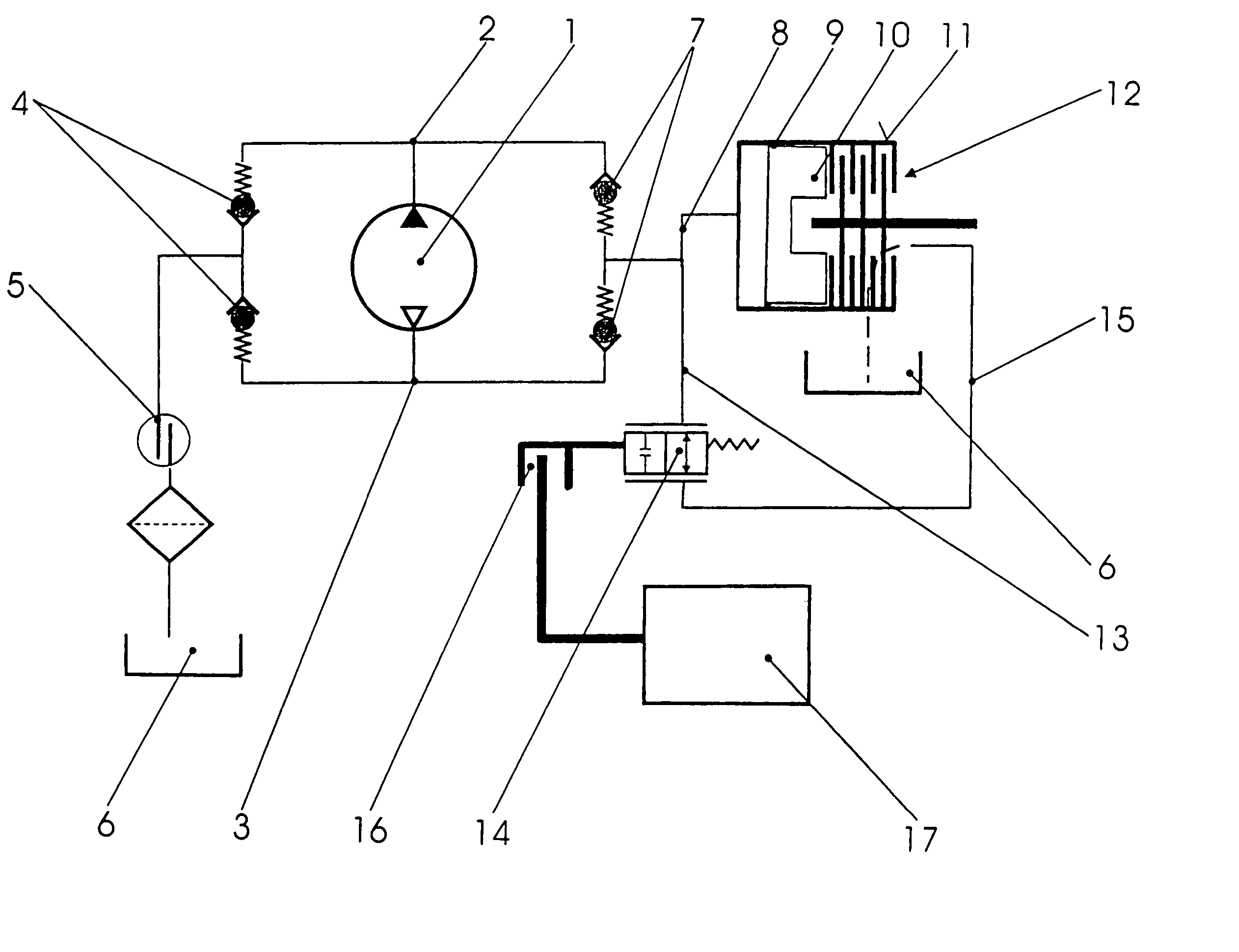
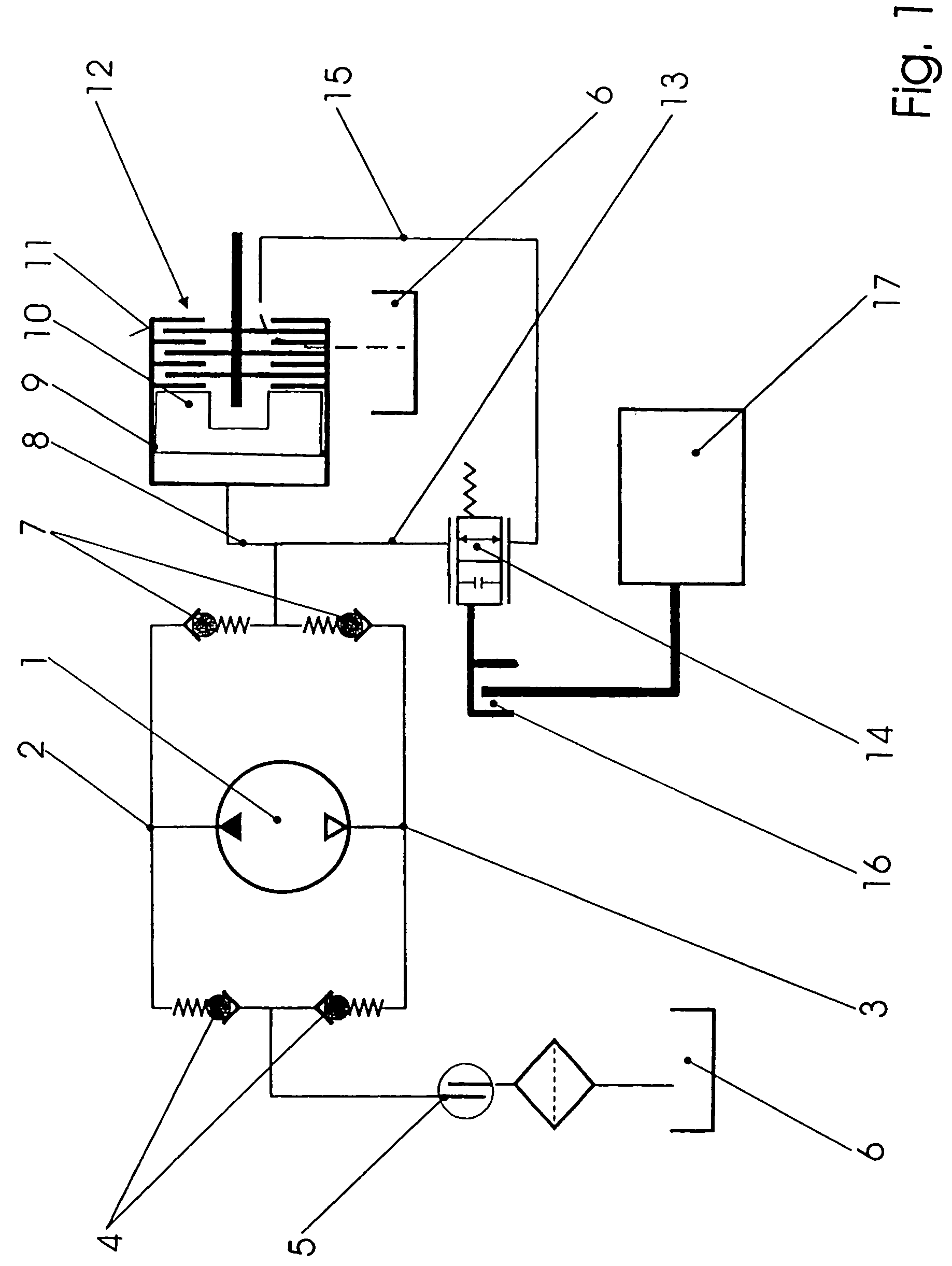
[0017]In FIG. 1, a hydrostatic displacement machine 1 is merely indicated without its connection to the elements of the speed-difference-dependent hydraulic clutch. Reference is made for this purpose to FIG. 2. The machine has a pressure chamber 2 or 3 and a suction chamber 3 or 2, depending on the mathematical sign of the difference in speed. The chambers 2, 3 are connected via non-return valves 4 on the intake side and a rotary input 5 to a sump 6, from which the intake is drawn. On the other side, the chambers 2, 3 are connected via non-return valves 7 on the delivery side and a pressure line 8 to a pressure space 9, in which they act on a piston 10 which is guided in a drive housing 11. By means of the pressure in the pressure space 9, the plates or discs of a clutch 12 are brought into contact and the clutch is thus more or less closed.

[0018]A passage 13 with a control valve 14 branches off from the pressure line 8. From said passage, a line 15 leads to the sump 6, here for the...


PUM


Abstract

A speed-difference-dependent hydraulic clutch comprises a drive housing (11), which rotates in a housing (20), a first shaft (21) which can be connected in a rotationally fixed manner to the drive housing, a second shaft (22) which is connected in a rotationally fixed manner to the drive housing, and furthermore a hydrostatic displacement machine (1), a friction clutch (12) for connecting the first shaft (21) to the drive housing (11), and a piston (10) for acting on the friction clutch (12), the drive housing (11) having a pressure space (9) and where a pressure is produced in the pressure space (9) when a difference in speed occurs in the pressure space (9), this pressure giving rise to action upon the friction clutch (12), and a passage (13) leading from the pressure space to a control valve which opens up the route to a space of lower pressure in a controlled manner.

Description

BACKGROUND OF THE INVENTION[0001]The invention relates to a speed-difference-dependent hydraulic clutch which comprises a drive housing, which rotates in a housing that is fixed in space and forms a reservoir for a working fluid, a first shaft which can be connected in a rotationally fixed manner to the drive housing, a second shaft which is connected in a rotationally fixed manner to the drive housing, and furthermore a hydrostatic displacement machine, a friction clutch for connecting the first shaft to the drive housing and a piston for acting on the friction clutch, which are accommodated in the drive housing, the drive housing having a pressure space, and where a pressure is produced in the pressure space when a difference occurs between the speed of the drive housing and that of the second shaft, this pressure giving rise to action upon the friction clutch, and a passage leading from the pressure space to a control valve which opens up the route to a space of lower pressure in...

Claims


Application Information

Patent Timeline
IPC IPC(8): F16D43/284F16D25/0638F16D48/02
CPCF16D25/0638F16D43/284Y10T477/70
Inventor GRATZER, FRANZSCHAFFERNAK, ROBERT
Owner MAGNA STEYR POWERTRAIN
Why Eureka
Try Eureka