Solenoid actuated variable pressure relief valve assembly for torque transfer assembly

a torque transfer and variable pressure relief valve technology, applied in fluid gearings, transportation and packaging, gearing, etc., can solve the problems of reducing fuel efficiency, wasting motive power, and slipping between the road surface and the tire, so as to improve the electronic control of the torque transfer assembly, simple constitution and cost low

Inactive Publication Date: 2006-07-18
DANA AUTOMOTIVE SYST GRP LLC
View PDF16 Cites 6 Cited by
  • Summary
  • Abstract
  • Description
  • Claims
  • Application Information

AI Technical Summary

Benefits of technology

[0020]The present invention provides an improved electronically controlled torque transfer assembly. Accordingly, the present invention provides a four-wheel-drive vehicle which does not have the above-described drawbacks and problems but which fulfills the functions of four-wheel drive under all conditions and whose constitution and cost are simple and low, respectively.
[0024]Therefore, the torque transfer assembly in accordance with the present invention allows to dynamically control the hydraulic pressure of the hydraulic clutch actuator for selectively frictionally loading the clutch pack.

Problems solved by technology

Occasionally, slip takes place between the road surface and the tire.
When the torque transmitted to the tire is so high that the tire slips, the torque does not fully act to propel the vehicle, resulting in wasted motive power, lowered fuel efficiency, and adverse vehicle handling.
Moreover, it is sometimes difficult to maintain the direction of movement of the vehicle in the case of locking of the rear wheel (in particular, in braking).
Although the part time-four-wheel-drive vehicle can be manufactured at a relatively low cost, it is troublesome to shift between the two-wheel drive and the four-wheel drive and it is likely that the vehicle is slowly turned when the driver mistakenly fails to properly choose between four-wheel drive and two-wheel drive.
These full-time four-wheel-drive vehicles suffer from a problem that no motive power is transmitted to any of the remaining three of four driving wheels when one wheel is caused to spin or loses the tire grip due to overhanging on the road side or ditch, a slip on an icy road, or the like.
As for the mechanical type, it is difficult to set a differential locking start time point, the time point cannot be changed depending on the moving condition of the vehicle, and it is more difficult to automate the differential locking mechanism.
As for the electronic control type, a device for controlling the differential locking mechanism is more complex and the cost of production of the mechanism is very high.
The conventional torque coupling assemblies, however, suffer from drawbacks inherent in their assembly and location within the vehicle drivetrain.

Method used


Image

  • Solenoid actuated variable pressure relief valve assembly for torque transfer assembly
  • Solenoid actuated variable pressure relief valve assembly for torque transfer assembly
  • Solenoid actuated variable pressure relief valve assembly for torque transfer assembly

Examples


Embodiment Construction

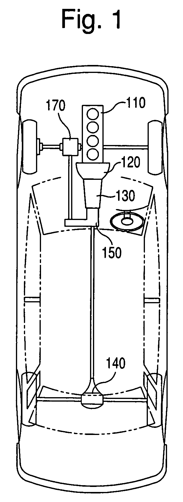
[0032]With reference to FIG. 1, the four-wheel-drive vehicle provided in accordance with the present invention comprises an engine 110, a transmission 130 which is driven through a clutch 120 by the engine 110 to change the speed of the output rotation of the engine 110. A transfer case 150 divides torque transmission between a first differential assembly 140 that drives one of a front and a rear wheel systems and a second differential assembly 170 that drives the other of the front and the rear wheel systems.

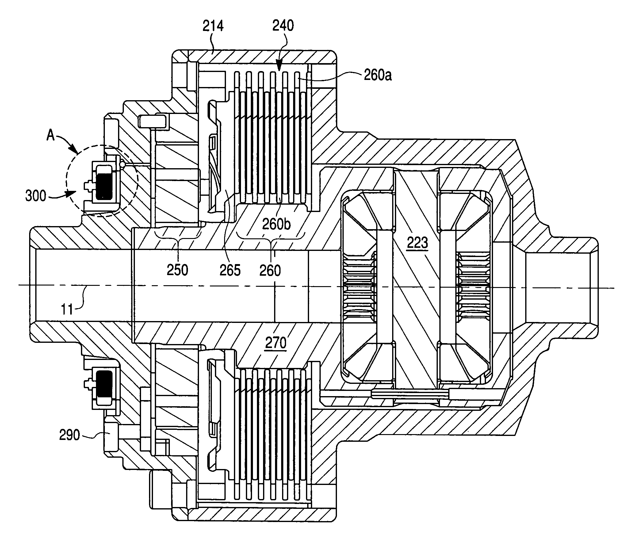
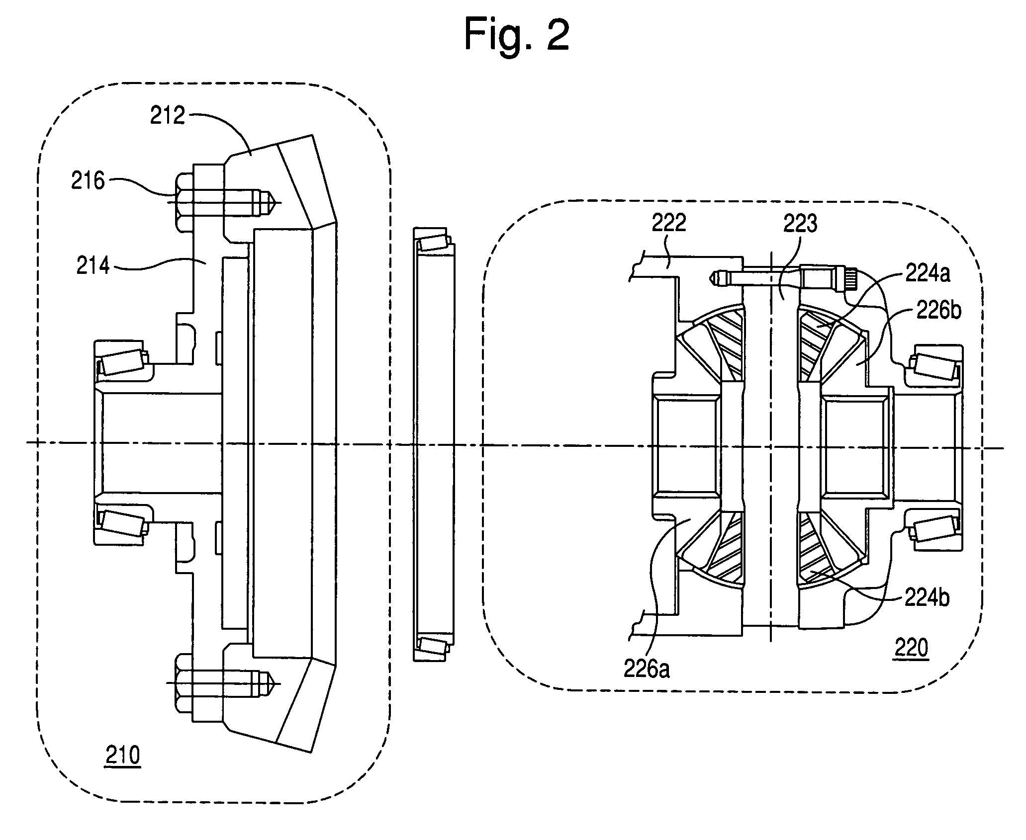
[0033]In accordance with this invention, a torque transmission coupling is provided between a ring gear and a planetary differential housing of one of the first and second differential assemblies 140, 170. The torque transmission coupling comprises an oil pump that is driven by the relative rotation between the ring gear sub-assembly and a planetary gear set sub-assembly to generate oil pressure corresponding to the speed of the relative rotation. A friction clutch mechanism en...


PUM


Abstract

A torque transfer assembly for a motor vehicle comprises a ring gear subassembly and a differential subassembly rotatably supported in said ring gear subassembly, a friction clutch pack for coupling the ring gear subassembly to the differential subassembly, and a hydraulic clutch actuator for selectively frictionally loading the clutch pack. The hydraulic clutch actuator includes a variable pressure relief valve assembly to selectively control the friction clutch pack. The variable pressure relief valve assembly includes a valve closure member, a valve seat complementary to the valve closure member, and a electro-magnetic actuator for engaging the valve closure member and urging thereof against the valve seat with an axial force determined by a magnitude of an electric current supplied to the electro-magnetic actuator so as to selectively vary a release pressure of the pressure relief valve assembly based on the magnitude of the electric current.

Description

[0001]This application is a Continuation-In-Part of U.S. patent application Ser. No. 10 / 083,138 filed Feb. 27, 2002 now U.S. Pat. No. 6,692,396.BACKGROUND OF THE INVENTION[0002]1. Field of the Invention[0003]The present invention relates to torque transfer assemblies for motor vehicles, and more particularly to a torque transfer assembly having an electronically controlled hydraulic actuator including an electromagnet actuated variable pressure relief valve.[0004]2. Description of the Prior Art[0005]Torque applied to a tire through a drive shaft propels a vehicle by the friction between the tire and the surface of the road for the vehicle. Occasionally, slip takes place between the road surface and the tire. The ratio of the slip depends on the coefficient of friction between the tire and the road surface. The coefficient of friction fluctuates due to the states of the road surface and the tire, the grounding load upon the tire, the magnitude of the torque transmitted to the tire, t...

Claims


Application Information

Patent Timeline
Patent Type & Authority Patents(United States)
IPC IPC(8): F16H48/30F16H47/08F16H48/06F16H48/20F16H48/22B60K23/04B60K17/35F16D43/284F16D48/02F16H48/08F16H48/32F16H48/34
CPCF16D43/284F16H48/08F16H48/22F16H48/34F16H48/30B60K17/20F16H2200/2071F16H48/32F16H2048/204F16H2048/346
Inventor YOSHIOKA, JUNGROGG, JOHN A.WUDY, JEREMY J.KAPLAN, MARTIN
Owner DANA AUTOMOTIVE SYST GRP LLC
Why Eureka
Try Eureka