Syringe and method of using
a syringe and plunger technology, applied in the field of syringe and method of use, can solve the problems of inability to handle a larger syringe using only one hand, inadvertent contact of the plunger shaft, touch contamination, etc., to prevent accidental separation of the plunger member, and be more stable and safer to work with or store.
- Summary
- Abstract
- Description
- Claims
- Application Information
AI Technical Summary
Benefits of technology
Problems solved by technology
Method used
Image
Examples
second embodiment
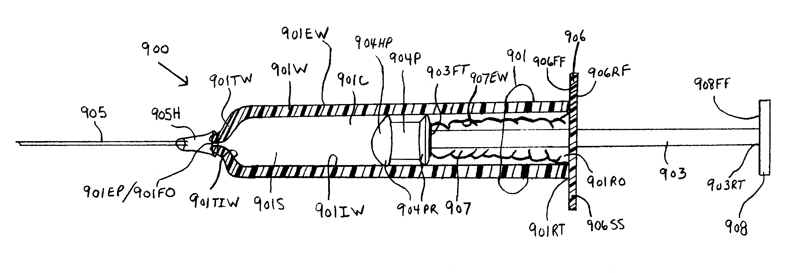
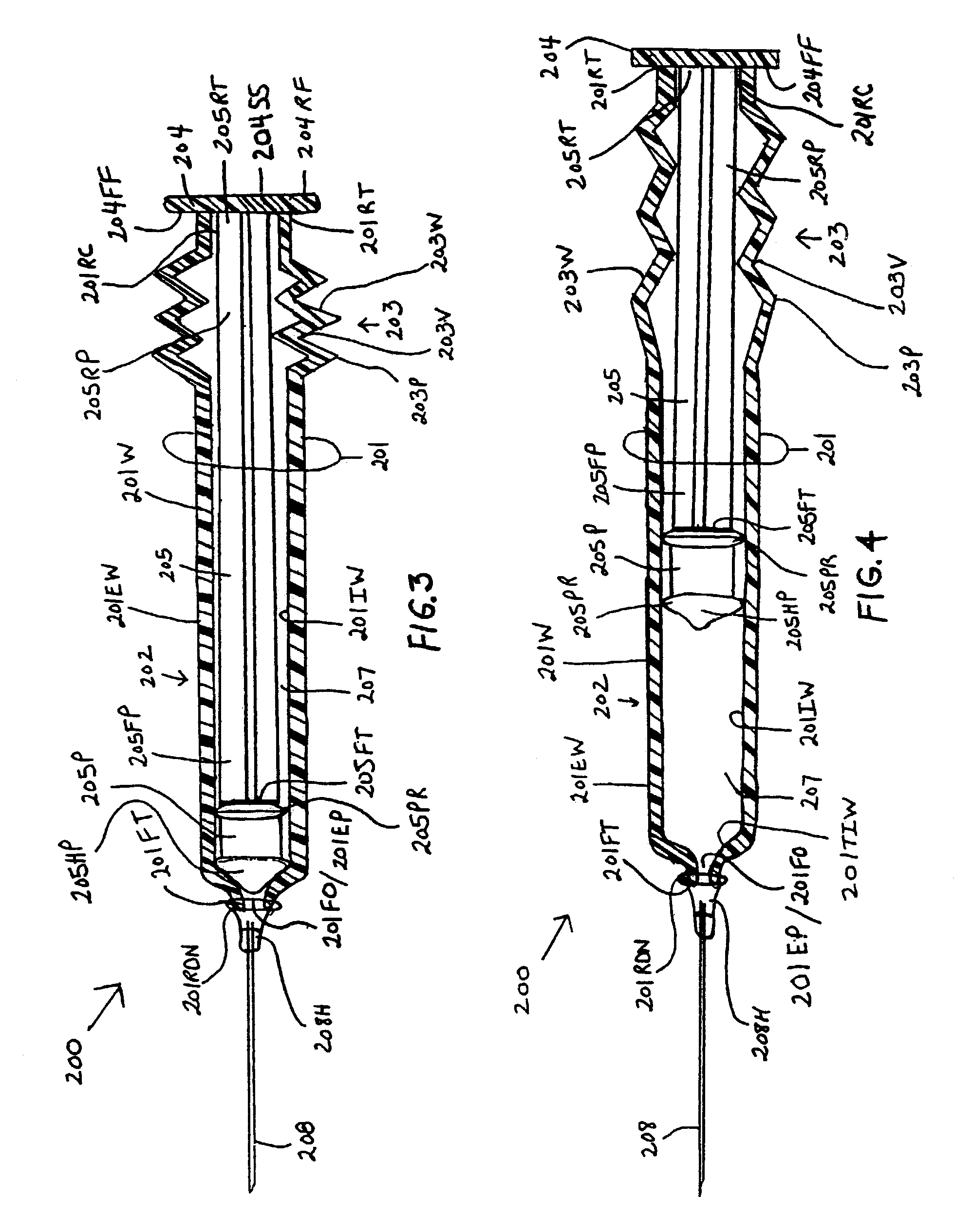
[0098]the instant invention, as shown by FIG. 3, illustrates a new and improved syringe 200 formed of a cylindrical syringe barrel 201 and a cylindrical plunger member 205. The syringe barrel 201 is formed with a straight segment 202 and a corrugated segment 203. The straight segment 202 is located on the forward end section of the syringe barrel 201 and the corrugated segment 203 is located at the rearward end section of the syringe barrel 201. The rearward end terminus 201RT of the syringe barrel 201 is molded to at least one surface of a plunger handle member 204. The at least one surface includes, but is not limited to, the forward face surface 204FF, the rearward face surface 204RF, and the side surface 204SS. The rearward end terminus 205RT of the plunger shaft 205 is centrally molded to the forward face surface 204FF of the plunger handle member 204. A rearward end portion 205RP of the plunger shaft body 205 is enclosed or surrounded by the corrugated segment 203 of the syrin...
third embodiment
[0101]the instant invention, as shown by FIGS. 5, 6A and 6B, illustrates a new and improved syringe 300 formed of a cylindrical syringe barrel 301 and a cylindrical plunger member 302. The syringe barrel 301 and the plunger member 302 have mating concentric plunger member and syringe barrel walls 302W and 301W, respectively. The plunger member 302 has a wall 302W having an open-end 302OE and a closed end 302CE. The closed end 302CE of the plunger member 302 has a flat bottom floor structure 304 forming a cup-shaped inner cavity. It is noted that other shapes can be used for the bottom floor structure; and thus, the shapes are not restricted to flat. The flat bottom floor structure 304 has forward and rearward face surfaces 304FF and 304RF, respectively. The flat bottom floor structure 304 can be molded continuous with the plunger member cylindrical walls 302W. The inside diameter of the plunger member 302 is constant along its length. The forward face surface 304FF of the flat botto...
fourth embodiment
[0106]the instant invention, as shown by FIGS. 7, 8A and 8B, illustrates a new and improved syringe 400 formed of cylindrical concentric syringe barrels 401OB and 401IB and a cylindrical plunger member 402. The plunger member 402 has a wall 402W with a forward open-end 402FO and a rearward closed end 402RC. The rearward closed end 402RC of the plunger member 402 has a flat bottom floor structure 403 forming a cup. It is noted that other shapes can be used for the bottom floor structure; and thus, the shapes are not restricted to flat. The flat bottom floor structure 403 has forward end and rearward end face surfaces 403FF and 403RF, respectively. The flat bottom floor structure 403 can be molded continuous with the walls of the plunger member 402W. The inside diameter of the plunger member walls 402W is constant along the length of the plunger member 402. The forward end face surface 403FF of the flat bottom floor structure 403 has molded thereto the rearward end terminus 404RT of a...
PUM
 Abstract
Description
Claims
Application Information
 - R&D
- Intellectual Property
- Life Sciences
- Materials
- Tech Scout
- Unparalleled Data Quality
- Higher Quality Content
- 60% Fewer Hallucinations
Browse by: Latest US Patents, China's latest patents, Technical Efficacy Thesaurus, Application Domain, Technology Topic, Popular Technical Reports.
© 2025 PatSnap. All rights reserved.Legal|Privacy policy|Modern Slavery Act Transparency Statement|Sitemap|About US| Contact US: help@patsnap.com


